
Mold clamping device and mold thickness adjusting method

A technology of mold clamping device and adjustment method, which is applied in the field of mold clamping device and mold thickness adjustment, and can solve the problems of more parts and lower accuracy of mold thickness adjustment

Inactive Publication Date: 2007-03-21
SUMITOMO HEAVY IND LTD
View PDF0 Cites 17 Cited by
  • Summary
  • Abstract
  • Description
  • Claims
  • Application Information

AI Technical Summary

Problems solved by technology

[0009] However, in the above-mentioned conventional mold clamping device, it is necessary to move not only the movable platen and the suction plate but also the back plate when adjusting the mold thickness, so many parts need to be moved, and the adjustment accuracy of the mold thickness is lowered.

Method used


Image

  • Mold clamping device and mold thickness adjusting method
  • Mold clamping device and mold thickness adjusting method
  • Mold clamping device and mold thickness adjusting method

Examples


Embodiment Construction

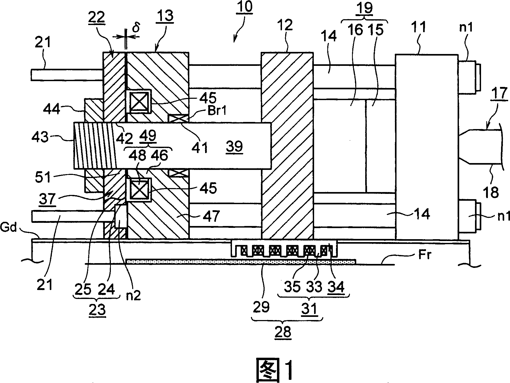
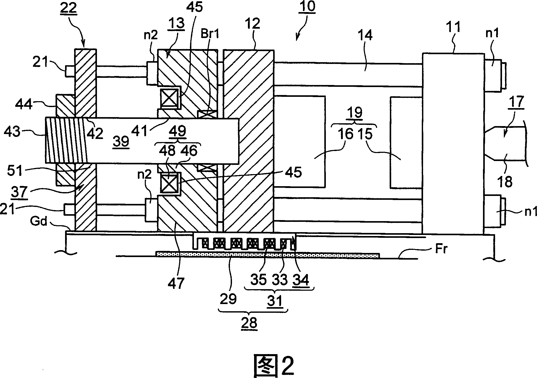
[0053] Embodiments of the present invention will be described in detail below with reference to the drawings. In addition, in this embodiment, the mold clamping device uses the moving direction of the movable platen when closing the mold as the front and the moving direction of the movable platen when opening the mold as the rear, and the injection device uses the The moving direction of the screw during injection is described as the front, and the moving direction of the screw during metering is described as the rear.

[0054] FIG. 1 shows the mold closing state of the mold device and the mold clamping device according to the first embodiment of the present invention, and FIG. 2 shows the mold opening state of the metal mold device and the mold clamping device according to the first embodiment of the present invention.

[0055] In the figure, 10 is a mold clamping device, Fr is a frame of an injection molding machine, and Gd is two guides that are laid on the frame Fr to cons...


PUM


Abstract

A mold clamping device (10) where less parts are required to move in mold thickness adjustment and accuracy in the mold thickness adjustment is increased. The mold clamping device has a first fixing member to which a fixed metal mold (15) is attached, a first movable member that is provided opposite the first fixed member and to which a movable metal mold (16) is attached, and a second movable member that is advanced and retreated as the first movable member is advanced and retreated. Mold thickness adjustment is made by changing relative positions of the first and second movable members. In this construction, since thickness adjustment is made by changing relative positions of the first and second movable members, less parts are required to move in the mold thickness adjustment, and as a result, accuracy of thickness adjustment is increased.

Description

technical field [0001] The invention relates to a mold clamping device and a mold thickness adjusting method. Background technique [0002] A conventional molding machine, such as an injection molding machine, includes an injection device, a mold device, and a mold clamping device. The resin is injected from the nozzle of the injection device, filled into the cavity space of the mold device, and cured to obtain a molded product. Furthermore, the mold device includes a fixed mold and a movable mold, and by operating the mold clamping device to advance and retreat the movable mold relative to the fixed mold, mold closing, mold clamping, and mold opening can be performed. [0003] The mold clamping device includes a fixed platen on which the fixed metal mold is mounted, a movable platen on which the movable metal mold is mounted, an electric motor, a ball screw shaft connected to an output shaft of the motor, and the ball screw shaft connected to the motor. A ball screw compos...

Claims


Application Information

Patent Timeline
Patent Type & Authority Applications(China)
IPC IPC(8): B29C45/66B29C33/22B29C45/17
CPCB29C2045/1793B29C45/1751B29C2045/645B29C45/66
Inventor 德井洋介守谷幸次
Owner SUMITOMO HEAVY IND LTD
Learn More