Electrical connector

An electrical connector, anchoring technology, applied in electrical components, circuits, parts of connecting devices, etc., can solve problems such as low impedance and larger gaps, and achieve the effect of firm connection

Inactive Publication Date: 2007-03-28
DDK LTD
View PDF2 Cites 1 Cited by
  • Summary
  • Abstract
  • Description
  • Claims
  • Application Information

AI Technical Summary

Problems solved by technology

In other words, even if the size of the housing mounting opening and the width dimension of the guide portion can be designed taking into account the thickness tolerance of the memory card, the gap will become large, resulting in low resistance to vibration and impact

Method used


Image

  • Electrical connector
  • Electrical connector

Examples


Embodiment Construction

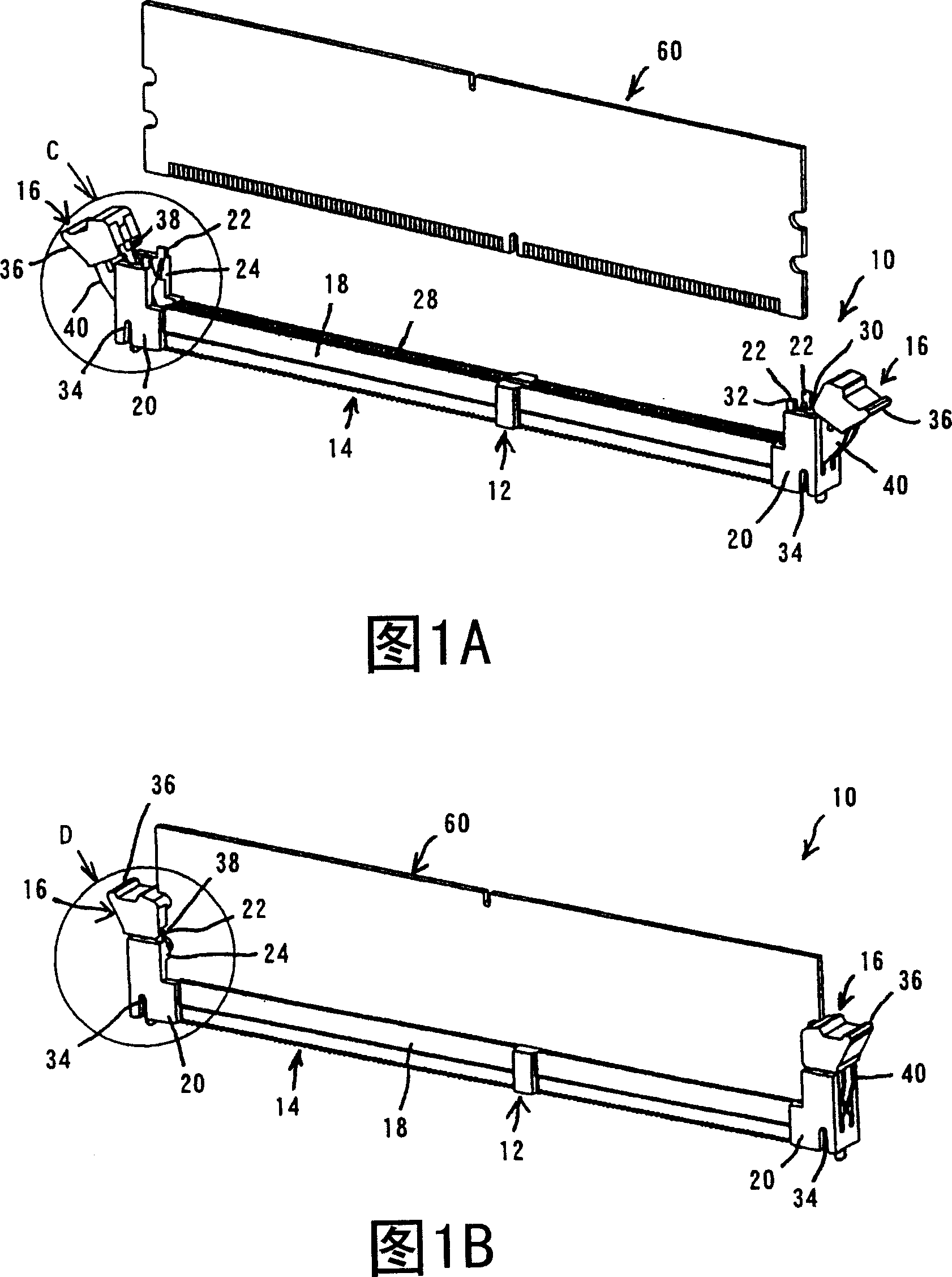
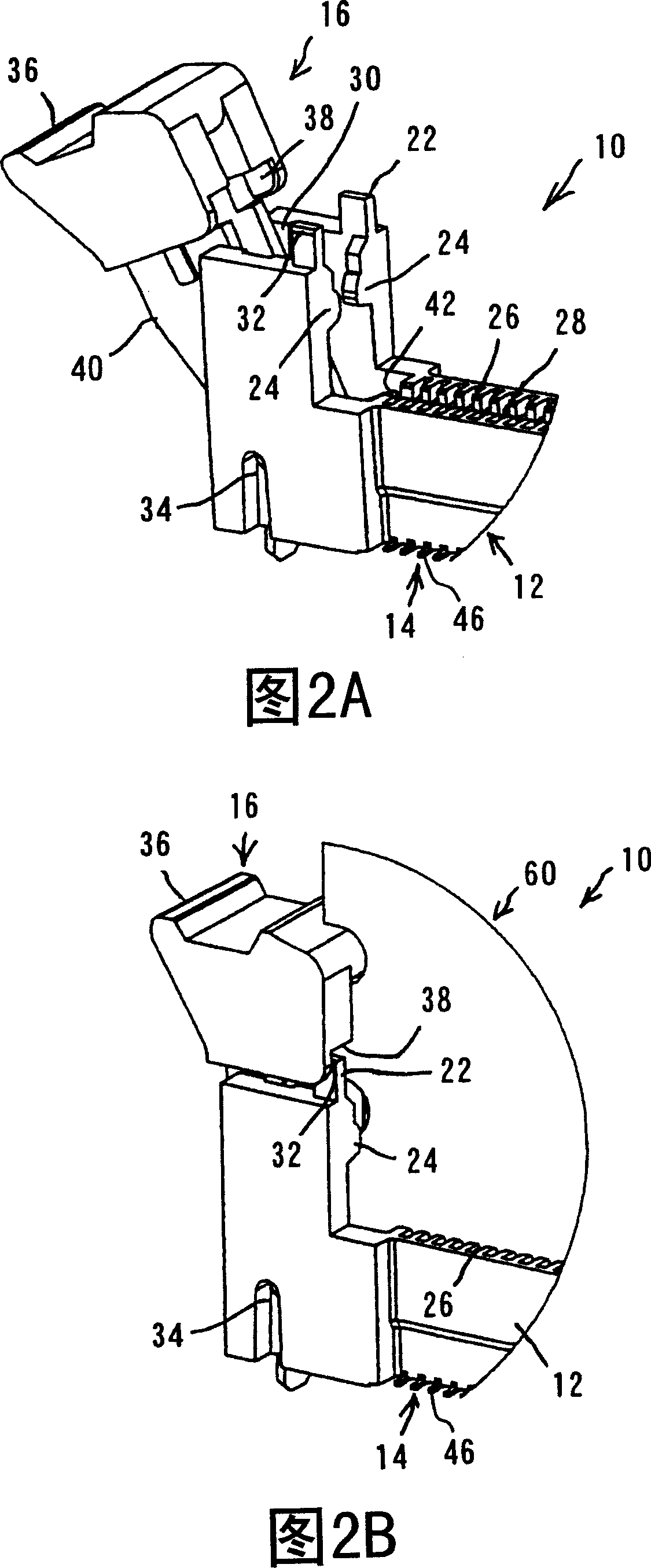
[0026] [020] An embodiment of an electrical connector according to the present invention will be explained with reference to FIGS. 1A to 2B. Fig. 1 A is the perspective view of memory card and electric connector according to the present invention seen from the side of the installation opening, and Fig. 1 B is the perspective view of the electric connector of the present invention with the memory card inserted from the side of the installation opening . 2A is a partially enlarged perspective view of the vicinity of the locking assembly of the electrical connector without a memory card inserted, and FIG. 2B is a partially enlarged perspective view of the vicinity of the locking assembly of the electrical connector inserted with a memory card.

[0027] [021] The electrical connector 10 according to the present invention generally includes a plurality of contacts 14, a housing 12 and a locking assembly 16.

[0028] [022] Before describing the components of the electrical connecto...


PUM


Abstract

An electrical connector includes a plurality of contacts, a housing arranging and holding the contacts and having a fitting opening into which a memory card is inserted, and pivotally movable locking members provided at both longitudinal ends of the housing, respectively, for holding and removing the memory card. The housing includes a main body for arranging and holding the contacts, and mounting portions provided at both the longitudinal ends for pivotally movably mounting the locking members. The mounting portions are each provided on both sides in width direction with protruding pieces extending against the inserting direction of the memory card. The locking members each include an anchoring portion adapted to engage and embrace the protruding pieces under a condition the memory card has been inserted. The electrical connector can comply with customers' requirements against vibration and does not cause any failed connection with a memory card even upon vibration and impact.

Description

technical field [0001] [001] The present invention relates to an electrical connector for electronic and electrical equipment such as servers, computers, etc., more particularly to an electrical connector with a strong anti-vibration and impact structure. Background technique [0002] [002] In the signal (information) exchange between the motherboard and the daughter board, a plurality of electrical connectors are fixed to the motherboard by welding or the like, and the daughter board is inserted into one electrical connector. In other words, each electrical connector includes at least one housing having a mounting opening for inserting a daughter card board therein, and contacts mounted and held in the housing and protruding into the mounting opening. [0003] In Patent Document 1 (Japanese Patent Application Publication No. 2002-94266) and Patent Document 2 (Japanese Patent Application Publication No. 2005-196058), the applicant of the present application has proposed this...

Claims


Application Information

Patent Timeline
Patent Type & Authority Applications(China)
IPC IPC(8): H01R12/16H01R13/639
CPCH01R23/7026H01R13/6275H01R23/7068H05K7/1409H01R12/721H01R13/6271H01R12/7029
Inventor 加藤宽道菊池仁古口康之羽石崇人
Owner DDK LTD
Why Eureka
Try Eureka