Luneberg lens antenna device

A technology of Lumberg lens antenna and antenna, which can be applied to antenna supports/installation devices, antennas, antenna parts and other directions, and can solve difficult and time-consuming problems.

Inactive Publication Date: 2007-03-28
SUMITOMO ELECTRIC IND LTD
View PDF0 Cites 17 Cited by
  • Summary
  • Abstract
  • Description
  • Claims
  • Application Information

AI Technical Summary

Problems solved by technology

In addition, the aforementioned anchors, etc. may be fixed in the wrong position, requiring repositioning or correction thereof
It is difficult and time-consuming to implement

Method used


Image

  • Luneberg lens antenna device
  • Luneberg lens antenna device
  • Luneberg lens antenna device

Examples


Embodiment Construction

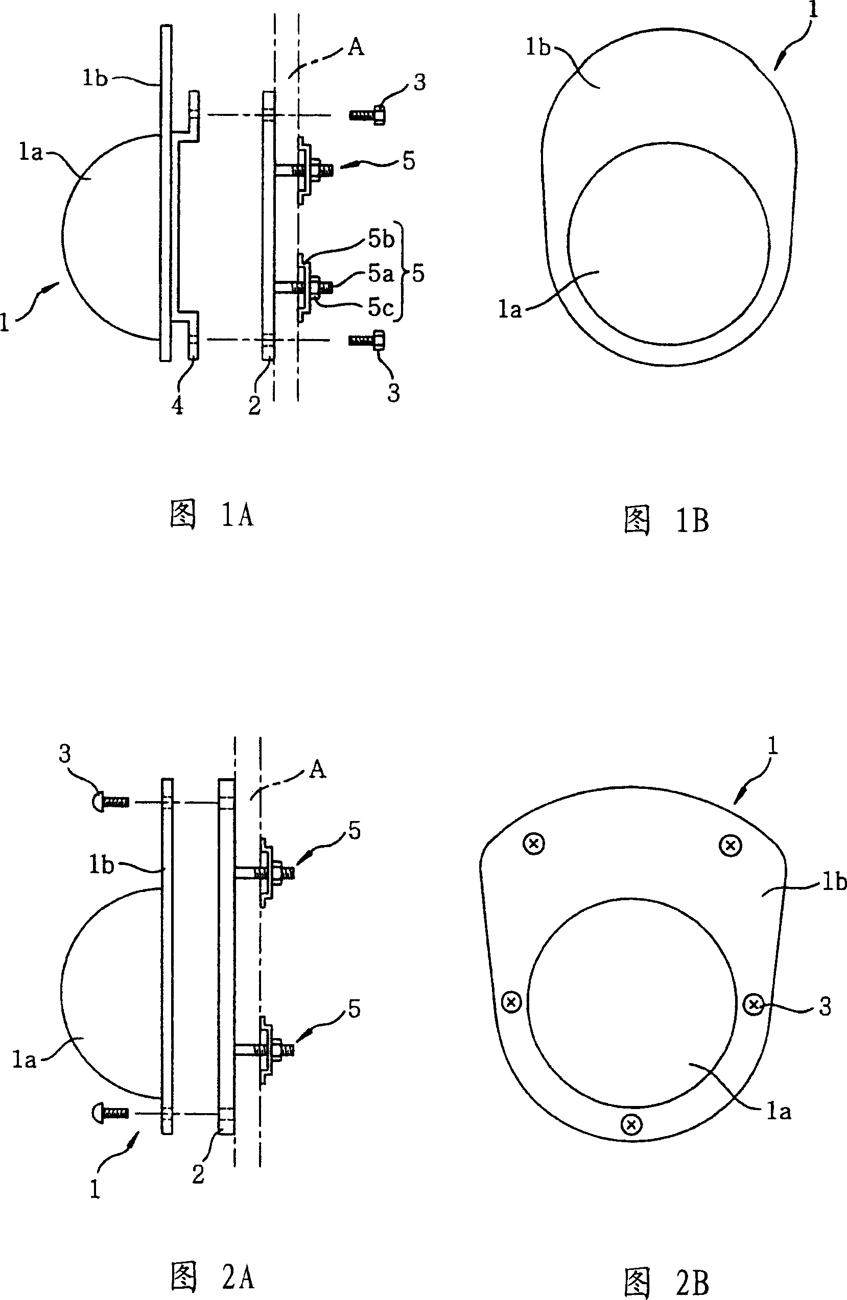
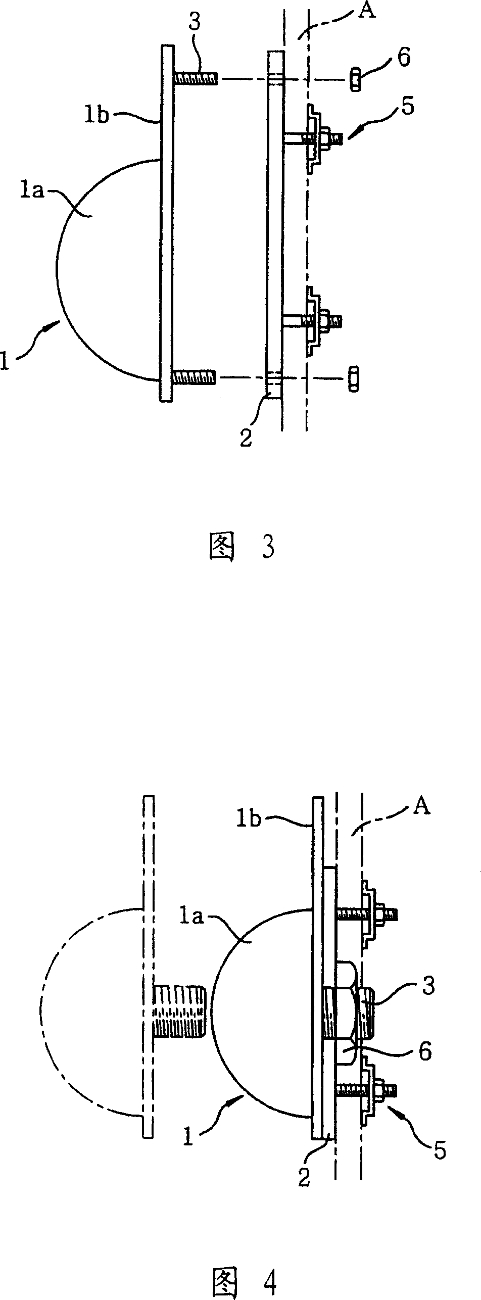
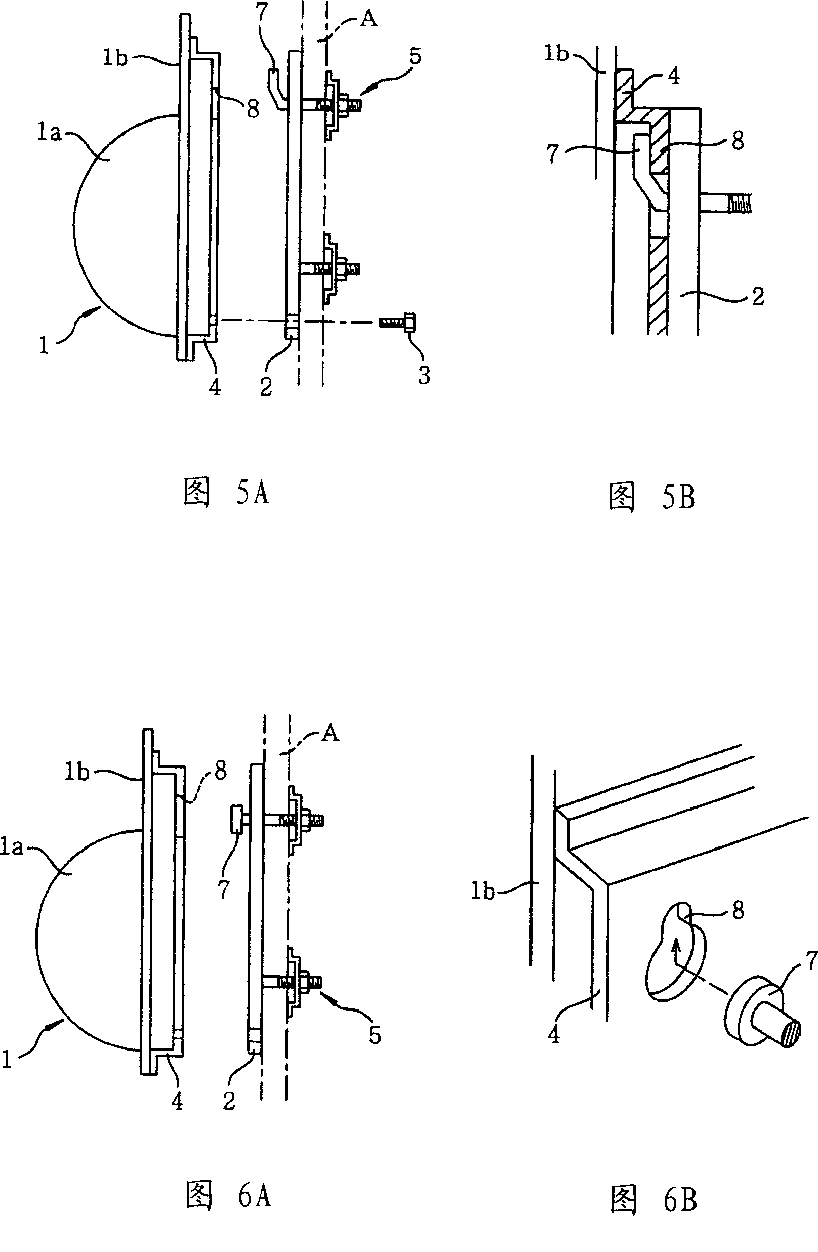
[0036] Next, preferred embodiments of the Lunberg lens antenna device according to the present invention will be described with reference to the accompanying drawings. The Lunberg lens antenna device shown in FIG. 1 includes: an antenna body 1 , an antenna fixing frame 2 and a bolt (fixing unit) 3 connecting the antenna body 1 to the antenna fixing frame 2 .

[0037] The antenna body 1 is composed of a hemispherical Luneberg lens 1a and a reflector 1b for reflecting radio waves. In addition to the antenna body 1, the Lunberg lens antenna device further includes: a cover covering the surface of the Lunberg lens 1a, a main radiator (LNB: Low Noise Block Downconverter) for receiving and transmitting radio waves, and an adjustable azimuth Angle to hold the elevation adjustable arm above the main radiator. These elements are not shown in the figure. These omitted components are attached to the antenna body 1 or the antenna holder 2 .

[0038] The attachment portion 4 is fixed on...


PUM


Abstract

An easy-to-install Luneberg lens antenna device constituted by combining a hemispherical Luneberg lens and a radio wave reflector. The Luneberg lens antenna device comprises an antenna fixing jig (2), and a fixing means, e.g., a bolt (3), for fixing the radio wave reflector (1b) of the antenna device (1) removably to the antenna fixing jig (2). The reflector (1b) and the antenna fixing jig (2) are previously provided, respectively, with fixing parts for fixing by the fixing means, the antenna fixing jig (2) is fixed to an antenna installing section and the reflector (1b) is fixed to the antenna fixing jig (2) by the fixing means.

Description

technical field [0001] The invention relates to an easy-to-install Luneberg lens device. Background technique [0002] The Lunberg lens antenna device has attracted attention because it is an antenna device that can transmit radio waves to and receive radio waves from multiple geostationary satellites. One of the Lunberg lens antenna devices combines a hemispherical Lunberg lens and a radio wave reflector for compactness or miniaturization, thereby obtaining functions equivalent to spherical lenses. [0003] For the Lunberg lens antenna device with a reflector, International Application No. PCT / JP2002 / 09179 (Reference 1) submitted by the applicant of the present application discloses such an installation method, wherein the reflector is fixed with screws or suspended Place it in the antenna installation area and connect it directly to the wall, etc. [0004] In a traditional parabolic antenna for satellite broadcast reception, it is necessary to fix the antenna in advance ...

Claims


Application Information

Patent Timeline
Patent Type & Authority Applications(China)
IPC IPC(8): H01Q1/12H01Q19/06
CPCH01Q1/1207H01Q1/1221H01Q19/065
Inventor 黑田昌利横田政夫
Owner SUMITOMO ELECTRIC IND LTD
Why Eureka
Try Eureka