
Automatic vending machine

A vending machine and casing technology, applied in the direction of instruments, coin-operated equipment for distributing discrete items, coin-operated equipment for distributing discrete items, etc., can solve vending machine failures, decreased work efficiency, wire burning To prevent problems such as breakage, to prevent the decline in work efficiency, reduce the possibility of failure, and reduce the possibility of leakage

Active Publication Date: 2012-07-18
FUJI ELECTRIC CO LTD
View PDF0 Cites 0 Cited by
  • Summary
  • Abstract
  • Description
  • Claims
  • Application Information

AI Technical Summary

Problems solved by technology

[0008] In a vending machine without a leakage circuit breaker, for example, when opening the door for maintenance, if between the voltage control unit and the electrical device, for example, the wires in it come into contact with foreign objects such as a screwdriver due to damage to the insulation material of the cable When a leakage occurs, it may cause the wire to burn out and cause the vending machine to malfunction.
[0009] On the other hand, in an automatic vending machine equipped with a leakage circuit breaker, for example, when the door leaf is opened for maintenance, if between the voltage control unit and the electrical device, for example, due to damage to the insulation material of the cable, the wires therein are disconnected from, for example, When a foreign object such as a screwdriver touches and causes leakage, although the leakage can be prevented by operating the leakage circuit breaker, after the leakage circuit breaker is activated, the operator must temporarily suspend the work, and in order to prevent the leakage from occurring again, the operation of the leakage circuit breaker must be released. operation, the operation can be restarted
Therefore, there is a problem that work efficiency is reduced due to job interruption

Method used


Image

  • Automatic vending machine
  • Automatic vending machine
  • Automatic vending machine

Examples


Embodiment Construction

[0026] Specific embodiments of the automatic vending machine according to the present invention will be described in detail below with reference to the accompanying drawings.

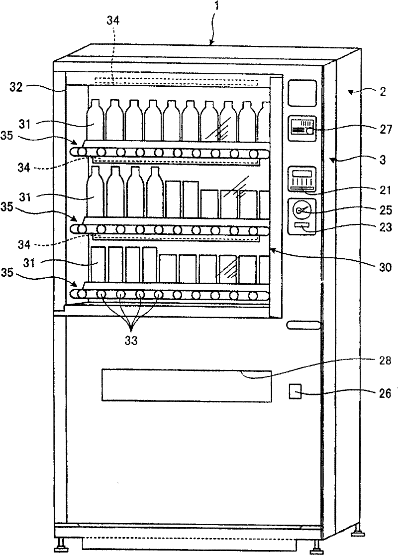
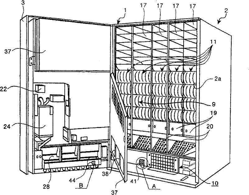
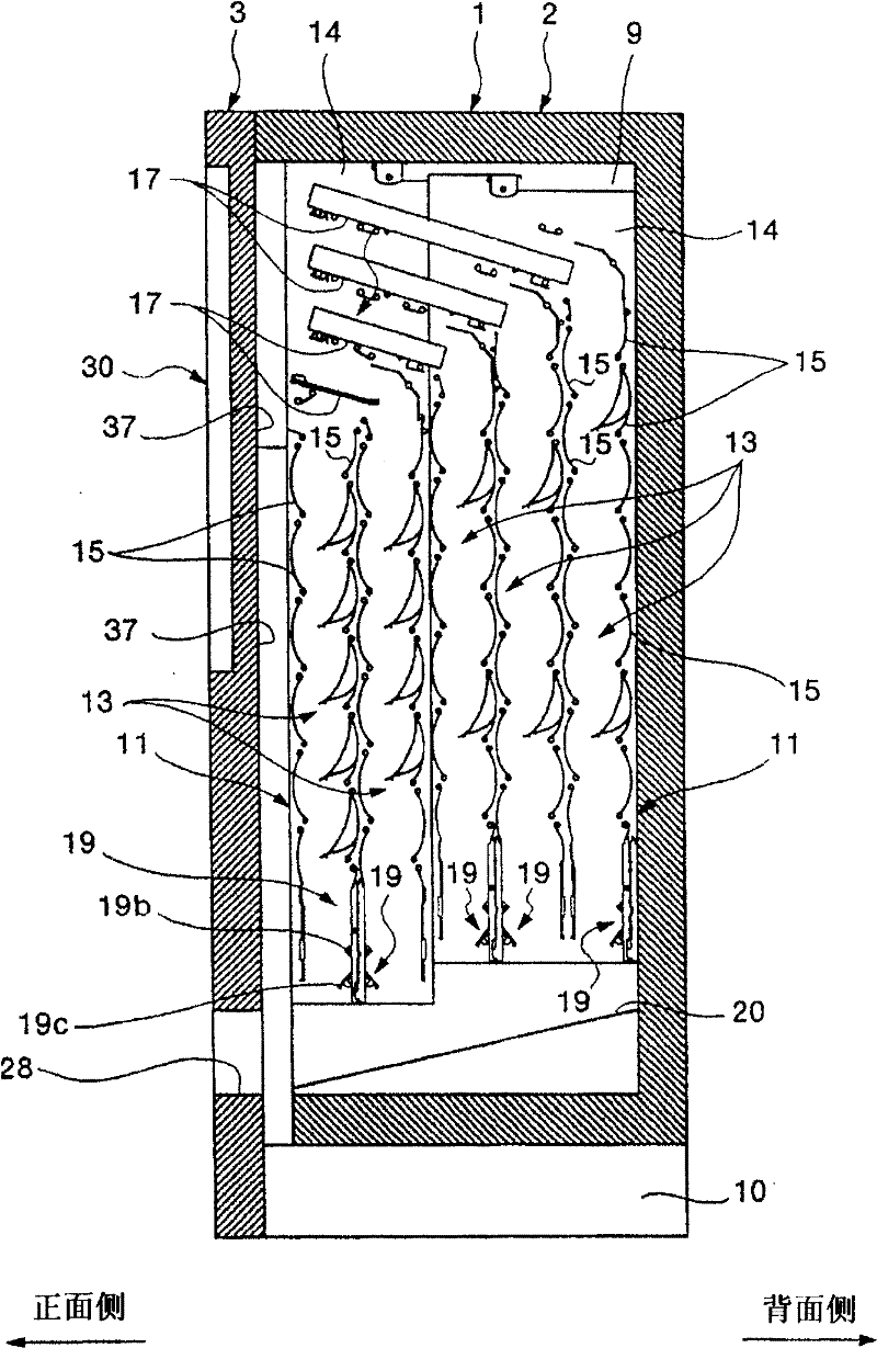
[0027] Figure 1 to Figure 3 The vending machine 1 according to the present invention is shown. The vending machine 1 illustrated here sells containerized beverages such as canned beverages, bottled beverages, soft-packed beverages, and plastic bottled beverages as commercial products, and a door (outer door) 3 is provided on the front surface of the main body casing 2 .

[0028] The main body casing 2 has a rectangular shape and is appropriately assembled from a plurality of steel plates, and an opening is formed on the front surface thereof.

[0029] The interior of the main body casing 2 is provided with Figure 4 Voltage control unit 4 shown. The voltage control unit 4 converts the voltage and frequency of the commercial power supply 5 into a predetermined voltage and frequency, and supplies the ...


PUM


Abstract

The present invention provides an automatic vending machine which can reduce the possibility of failure and the possibility of the operating efficiency declining during open doors to operating. The automatic vending machine (1) includes a door installed at the housing of main body switchable easily and electric apparatuses (19), (34) acting by voltage control unit 4 to supply voltage. The switching unit (40) is installed between the door and the housing of the main body, when the door is open, the switching unit (40) cuts off the voltage from the voltage control unit supplying to the electric apparatus, and when the door is close, and the switching unit allows the voltage control unit to supply voltage to the electric apparatus. Because the low voltage of the coins handling device (24) does not connected with the switching unit (40), it can recycle coins in the coins handing device, when the door is open, it can carry out action on the switch unit (40) connected with the to-be-discharged merchandise holding member (1) by handle.

Description

technical field [0001] The present invention relates to an automatic vending machine. Background technique [0002] For example, vending machines that sell containerized beverages such as canned beverages, bottled beverages, soft-packaged beverages, or plastic bottled beverages as merchandise have been widely used. This type of vending machine includes a door leaf that can be opened and closed on the main body casing, a voltage control unit and a product discharge mechanism (electrical device) provided inside the main body casing, and a lighting unit (electrical device) provided in the door leaf. [0003] The voltage control unit is used to convert the voltage and frequency of the commercial power supply into a predetermined voltage and frequency, and to supply the voltage to each electrical device. [0004] The product discharge mechanism is connected to the voltage control unit through a cable whose conductor is covered with an insulating material, and operates according ...

Claims


Application Information

Patent Timeline
Patent Type & Authority Patents(China)
IPC IPC(8): G07F11/00G07F9/00
Inventor 仓馨
Owner FUJI ELECTRIC CO LTD
Learn More