Pneumatic controlled material circulation device

A material circulation, pneumatic control technology, applied in the direction of burning fuel, lighting and heating equipment, fluidized bed combustion equipment, etc. Independent and reliable effects

Active Publication Date: 2007-04-18
INST OF ENGINEERING THERMOPHYSICS - CHINESE ACAD OF SCI
View PDF0 Cites 5 Cited by
  • Summary
  • Abstract
  • Description
  • Claims
  • Application Information

AI Technical Summary

Problems solved by technology

The advantages of mechanical valves are excellent adjustment characteristics and flexible operation control and adjustment; however, due to long-term work at high temperatures, mechanical valves have complex structures, easy jamming, easy wear, high material grades, and expensive

Method used


Image

  • Pneumatic controlled material circulation device
  • Pneumatic controlled material circulation device

Examples


Embodiment 1

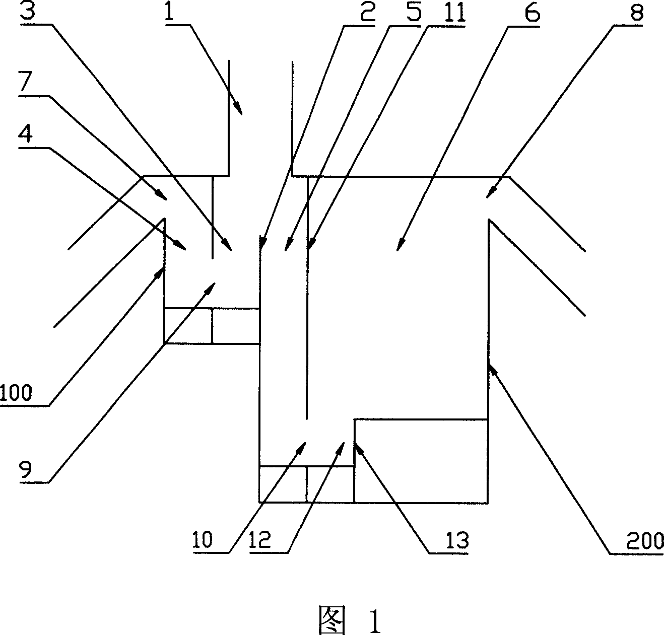
[0025] Fig. 1 is the structural representation of embodiment 1 of the present invention, as can be seen from the figure, the specific structure of the pneumatically controlled material circulation device of the present embodiment is as follows:

[0026] The pneumatically controlled material circulation device provided by the present invention includes: a feeder 100, and an external heat exchanger 200; the feeder 100 includes a feeder chamber 3, a feeder discharge chamber 4, two The bottom of the feeder is connected through the horizontal hole 9 of the feeder, and the upper part of the discharge chamber 4 of the feeder is provided with an overflow port 7 of the feeder;

[0027] The external heat exchanger 200 includes:

[0028] The feed chamber 5 of the external heat exchanger and the heat exchange chamber 6 of the external heat exchanger are separated by a partition plate 11 of the external heat exchanger, and the bottom communicates with each other through a horizontal hole 1...

Embodiment 2

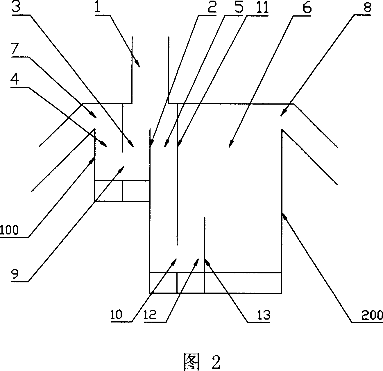
[0034] Fig. 2 is the structural representation of embodiment 2 of the present invention, as can be seen from the figure, the specific structure of the pneumatically controlled material circulation device of the present embodiment is as follows:

[0035] The pneumatically controlled material circulation device provided by the present invention includes: a feeder 100, and an external heat exchanger 200; the feeder 100 includes a feeder chamber 3, a feeder discharge chamber 4, two The bottom of the feeder is connected through the horizontal hole 9 of the feeder, and the upper part of the discharge chamber 4 of the feeder is provided with an overflow port 7 of the feeder;

[0036]The external heat exchanger 200 includes:

[0037] The feed chamber 5 of the external heat exchanger and the heat exchange chamber 6 of the external heat exchanger are separated by a partition plate 11 of the external heat exchanger, and the bottom communicates with each other through a horizontal hole 10...


PUM


Abstract

The invention comprises a return device and an external heat exchanger. One part of circulating ashes separated from a high-temp. gas-solid separator returns to the hearth directly and the other part enters into the external heat exchanger and then return to the hearth again after exchanging heat with the heat-exchanging surface. The ratio of the flow rate of the two parts of the circulating ashes is regulated by fluidized air, so as to realize the control of the circulating ash entered the external heat exchanger.

Description

technical field [0001] The invention relates to a material circulation device in a circulating fluidized bed combustion device, in particular to a pneumatically controlled material circulation device. Background technique [0002] Large-capacity circulating fluidized bed boilers often use external heat exchangers to solve the contradiction between heating surface layout and bed temperature adjustment; in order to improve steam parameters, circulating fluidized bed incinerators arrange steam superheaters in external heat exchangers to Avoid high temperature chlorine corrosion. In these occasions, the high-temperature circulating material is diverted from the main circulation loop, and then returned to the furnace, which requires the control of the circulation of the high-temperature material. The current material circulation control devices can be divided into two types: mechanical and non-mechanical. [0003] Mechanical valves mainly include conical valves widely used in L...

Claims


Application Information

Patent Timeline
Patent Type & Authority Applications(China)
IPC IPC(8): F23C10/02
Inventor 吕清刚高鸣那永洁包绍麟孙运凯贺军
Owner INST OF ENGINEERING THERMOPHYSICS - CHINESE ACAD OF SCI
Why Eureka
Try Eureka