Locking device

A locking device and locking technology, which are used in building locks, fastening devices for wing sashes, and building fastening devices, can solve problems such as damage, destruction, and expensive maintenance of locking components, and reduce damage. dangerous effect

Inactive Publication Date: 2007-04-18
FUJITSU SIEMENS COMP GMBH
View PDF0 Cites 11 Cited by
  • Summary
  • Abstract
  • Description
  • Claims
  • Application Information

AI Technical Summary

Problems solved by technology

[0004] If during daily work (Arbeitsalltag) documents are between the two half-housings of the notebook, they are caught in the locking device and are damaged by the locking element
Furthermore, when working with a notebook computer, there i

Method used


Image

  • Locking device
  • Locking device
  • Locking device

Examples


Example Embodiment

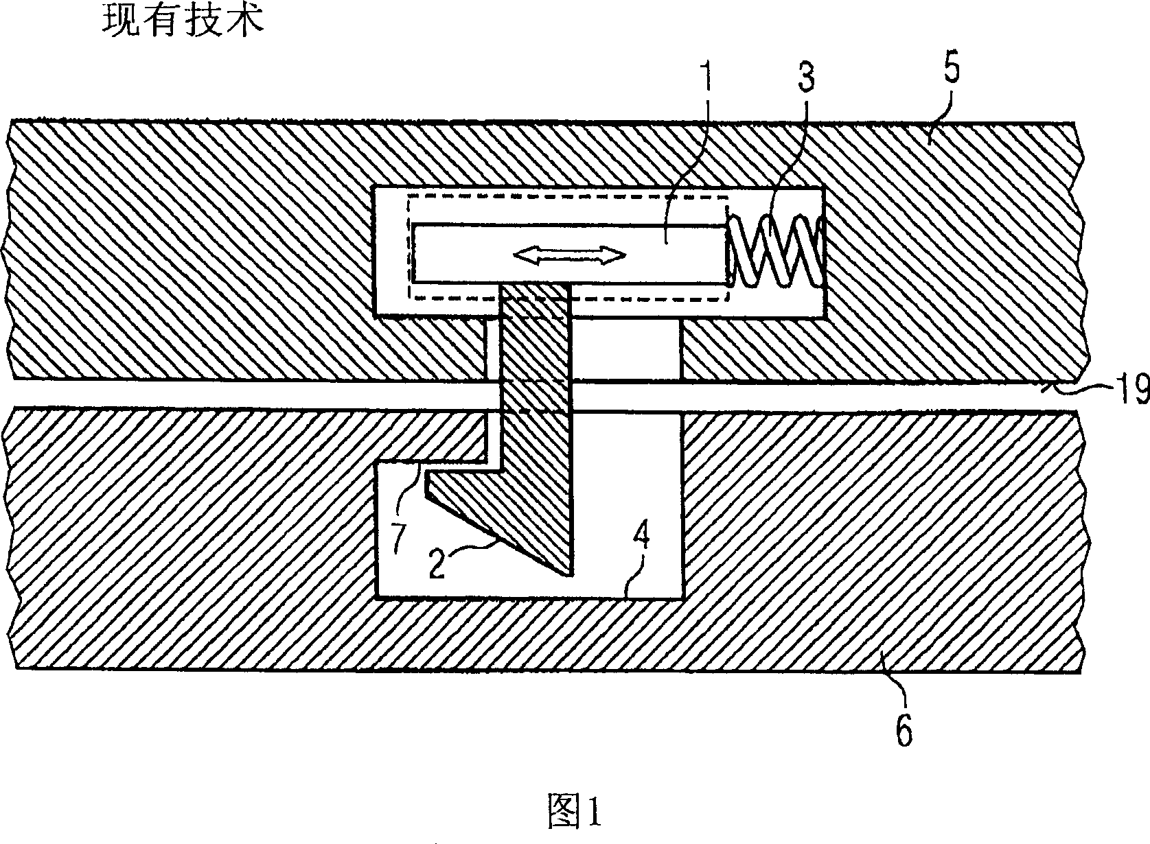
[0027] FIG. 1 shows a locking device according to the applicant's internal technology status, where the protruding locking element 2 is fixedly and immovably coupled with the operating element. In the schematic diagram of FIG. 1, in order to make the components located behind it more clear, only the operating element 1 that can be implemented in various forms is schematically shown. The external configuration of the operating element 1 is of secondary importance to the function of the locking element according to the invention. The spring 3 exerts its elastic force on the operating element 1 and therefore also directly acts on the protruding latching element 2 in one direction. The operating element 1, the spring 3 and the protruding locking element 2 are arranged on the first part 5 of the housing. The corresponding locking element 4 and the locking protrusion 7 provided in the locking element are arranged on the second part 6 of the housing. The elastic force of the spring 3 is ...


PUM


Abstract

The invention relates to a locking device used for locking a first component (5) together with a second component (6) when joining components (5 and 6) along a locking direction (8). The locking device comprises: a projecting rest element (2) on the first component (5), and a coressponding rest element (4) on the second component (6), wherein the projecting rest element (2) and the coressponding rest element (4) work together in a locking position of the components (5 and 6). The projecting rest element (2) is movably supported and a bearing unit (10) of the projecting rest element (2) is configured that the projecting rest element is relieved when a force is applied to the projecting rest element (2) along the locking direction (8).

Description

Technical field [0001] The invention relates to a locking device, which is used to lock the first part and the second part when the first part and the second part are combined together in the locking direction. Background technique [0002] The applicant has already known some locking devices from his own prior art, especially locking devices for notebook computers. In the July 2002 edition of "Lifebook C Series"; Fujitsu Siemens Computers published the prior art in the form of printed matter. [0003] The notebook computer whose two half shells (Gehaeusehaelften) are foldably connected to each other is locked by a locking device. In the locked state, the notebook computer is closed and the operating elements and display elements of the notebook computer are protected from mechanical damage. For this purpose, a locking device is provided, which is constructed with a locking element, an operating element, an elastic element and a corresponding locking element in such a way that th...

Claims


Application Information

Patent Timeline
IPC IPC(8): G06F1/16E05C19/10
CPCE05C5/00G06F1/1616E05B17/0058G06F1/1679E05C1/10
Inventor 理查德·赛博尔德
Owner FUJITSU SIEMENS COMP GMBH
Why Eureka
Try Eureka