

Crossflow fan
A cross-flow fan, a part of the technology, applied in the field of cross-flow fans, can solve the problem of high noise at the end of the tongue area
- Summary
- Abstract
- Description
- Claims
- Application Information
AI Technical Summary
Problems solved by technology
Method used
Image

Examples
Embodiment approach 1
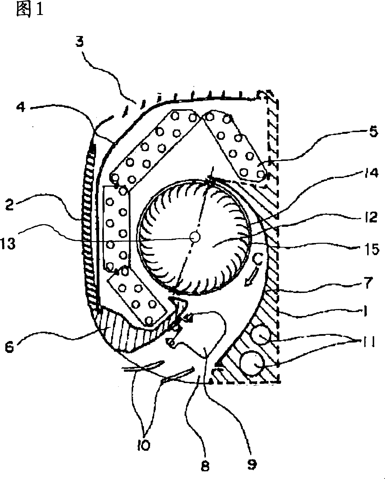
[0023] Fig. 1 is a cross-sectional view of an air conditioner using a cross-flow fan according to Embodiment 1 of the present invention. In the drawings, parts marked with the same symbol indicate the same or equivalent parts, and this is the case throughout the specification. In addition, the form of the structural element shown in the whole specification is an illustration, and is not limited to these descriptions.
[0024] In FIG. 1 , a front suction grill 2 is provided on the front of a housing 1 of the air conditioner, and a top suction grill 3 is provided on the upper surface. In the casing 1, along the front suction grille 2 and the upper suction grille 3, a filter 4 for removing dust contained in the air is provided, and along the filter 4, there is a filter 4 for the front suction grille 2 and the upper suction grille. A heat exchanger 5 for exchanging heat with the air sucked in by the suction grill 3 . At the front lower part of the housing 1, a protruding portion...
Embodiment approach 2
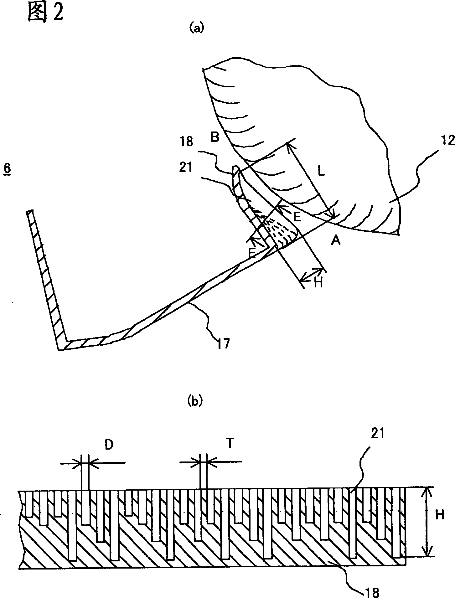
[0038] Embodiment 1 shows an air conditioner using a cross-flow fan in which at least some of the grooves have different depths H in the radial direction of the impeller 12 . Embodiment 2 of the present invention shows an air conditioner using a cross-flow fan in which at least some of the plurality of grooves have different lengths L in the circumferential direction of the impeller 12 .
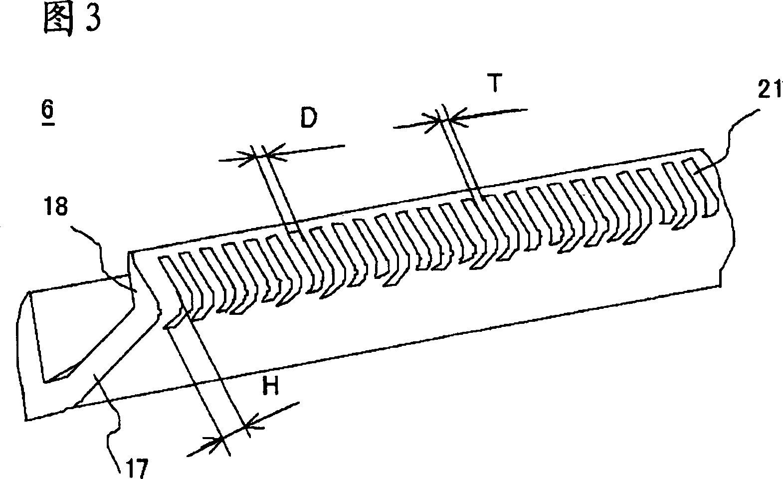
[0039] 5 is a cross-sectional view of a protruding portion of a cross-flow fan according to Embodiment 2 of the present invention on a plane perpendicular to the rotation axis. 6 is a perspective view of a protruding portion of a cross-flow fan according to Embodiment 2 of the present invention.
[0040] As shown in FIGS. 5 and 6 , the cross section of the tongue 18 on the plane perpendicular to the circumferential direction of the impeller 12 (the plane including the rotating shaft 13 of the impeller 12 ) is comb-shaped. A plurality of grooves 22 are arranged in parallel in the direction o...
Embodiment approach 3
[0049] Embodiment 1 shows an air conditioner using a cross-flow fan in which at least some of the grooves have different depths H in the radial direction of the impeller 12 . Embodiment 3 of the present invention shows an air conditioner using a cross flow fan in which at least some of the plurality of grooves have different widths D in the direction of the rotation axis 13 of the impeller 12 .
[0050] 8 is a perspective view of a protruding portion of a cross-flow fan according to Embodiment 3 of the present invention.
[0051] As shown in FIG. 8 , the cross section of the tongue 18 on the plane perpendicular to the circumferential direction of the impeller 12 (the plane including the rotating shaft 13 of the impeller 12 ) becomes comb-shaped. A plurality of grooves 23 are arranged in parallel in the direction of the rotating shaft 13 . Some of the plurality of grooves 23 have different shapes, and also have different widths D in the direction of the rotating shaft 13 of th...
PUM
 Abstract
Description
Claims
Application Information