
Wheel support device

一种支承装置、车轮的技术,应用在车轮、动力装置、控制装置等方向,能够解决车辆乘坐舒适性恶化等问题,达到抑制车辆乘坐舒适性的恶化、防止接触、降低强度的效果

Inactive Publication Date: 2007-05-02
TOYOTA JIDOSHA KK +1
View PDF0 Cites 10 Cited by
  • Summary
  • Abstract
  • Description
  • Claims
  • Application Information

AI Technical Summary

Problems solved by technology

If the outer frame comes into contact with other parts, noise and impact will be transmitted to the body, resulting in deterioration of the ride comfort of the vehicle

Method used


Image

  • Wheel support device
  • Wheel support device
  • Wheel support device

Examples


no. 1 example

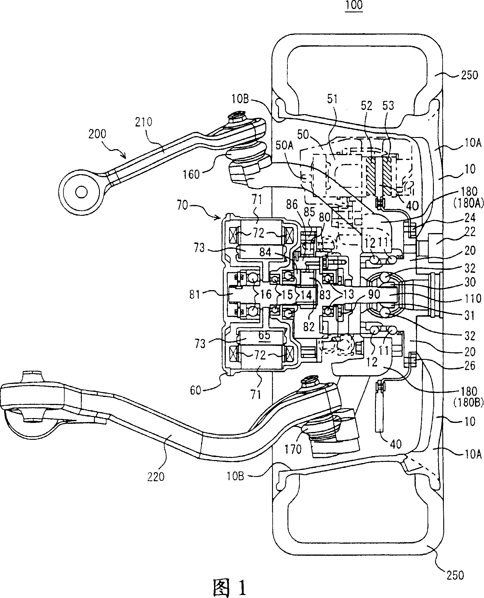
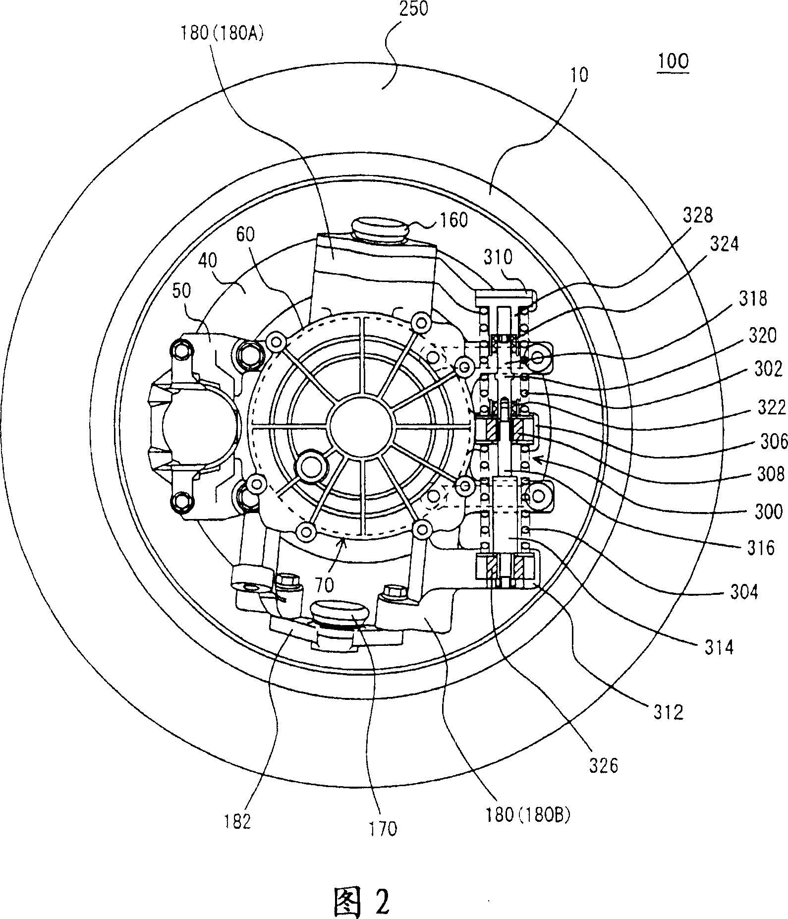
[0031] As shown in Figure 1, according to the first embodiment of the present invention, the electric wheel 100 supported by the wheel support device 200 is composed of a spoke 10, a hub 20, a constant velocity joint 30, a brake disc 40, a brake caliper 50, and an in-wheel motor. 70 and tire 250 are formed.

[0032] The in-wheel motor 70 is formed of a housing 60, a motor 65, a planetary gear 80, an oil pump 90, a shaft 110, and an oil passage (not shown).

[0033] The wheel support device 200 is formed of a dynamic mass damper mechanism (not shown), ball joints 160, 170, knuckle 180, upper arm 210, lower arm 220, and shock absorbers (impact absorbers, not shown).

[0034] The spoke 10 is substantially cup-shaped, and is formed of a disc portion 10A and a rim portion 10B. The spokes 10 may be configured to accommodate the hub 20 , the brake disc 40 , the brake caliper 50 and the in-wheel motor 70 . The spokes 10 are connected to the hub 20 by fastening the disc portion 10A t...

no. 2 example

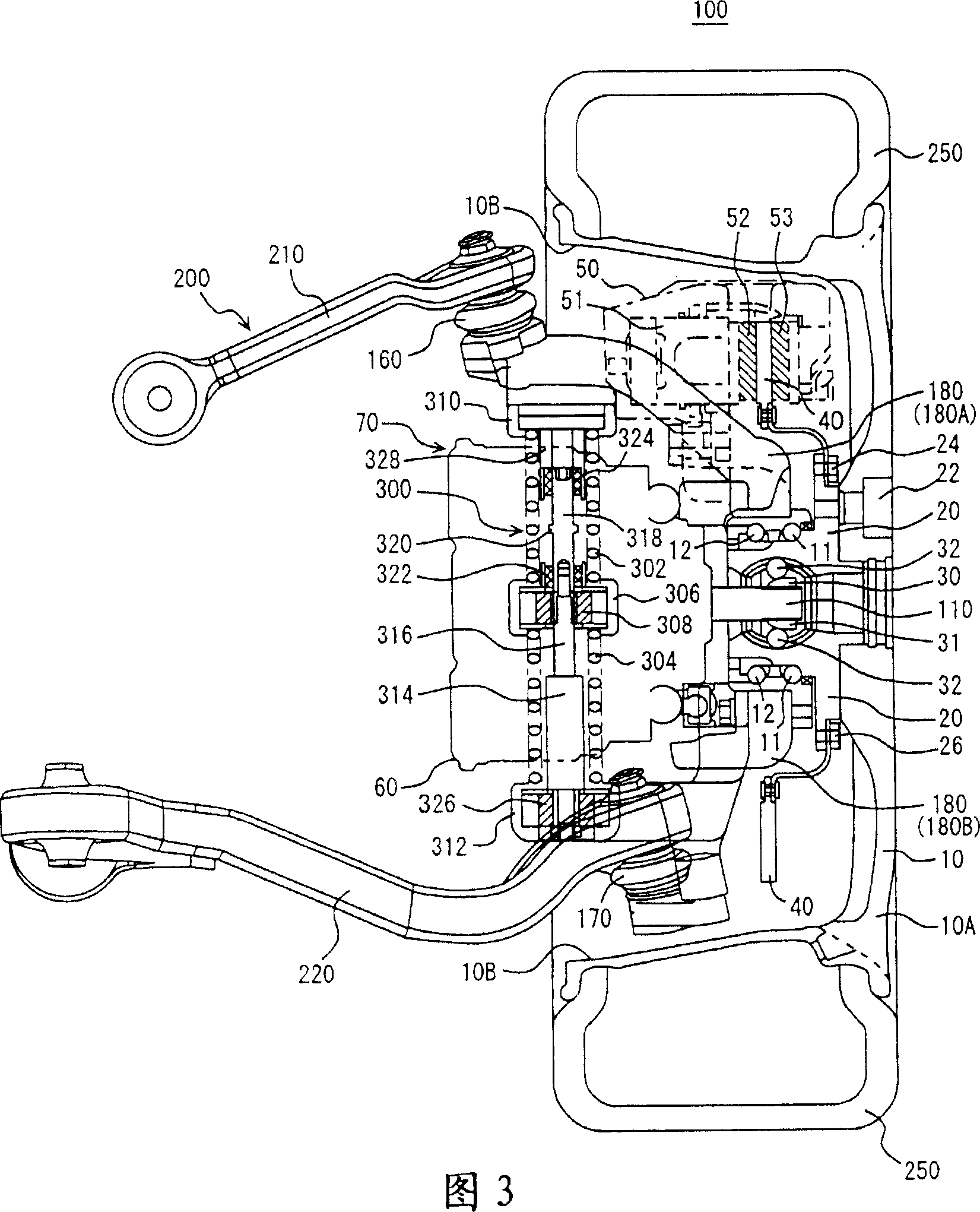
[0067] Next, a wheel supporting device of a second embodiment of the present invention will be described. Compared with the structure of the wheel support device 200 according to the first embodiment described above, the wheel support device according to the present embodiment is different in the structure of the shock absorber 314 and also differs in that instead of the buffer members 332 and 334, It includes cushioning members 332 and 334 . In other respects, its structure is the same as that of the wheel support device 200 according to the above-mentioned first embodiment. They are denoted by the same reference numerals, and their functions are the same. Therefore, detailed description thereof will not be repeated here.

[0068] The wheel supporting device 200 involved in the present invention is characterized in that it includes: a housing 60 vibrating with the vibration of the in-wheel motor 70; a steering knuckle 180 that limits the vibration of the motor by contacting...


PUM


Abstract

A wheel support device (200), comprises springs (302, 304) fitted to an in-wheel motor (70) and damping the vibration of a motor-driven wheel (100) and the in-wheel motor (70) by extending and retracting, a knuckle (180) mounted on the springs (302, 304) and rotatably supporting the motor-driven wheel (100), the center part (306) of a dynamic mass damper mechanism (300) vibrating together with the in-wheel motor (70) by a force given from a road surface when a vehicle runs, the upper part (310) thereof restricting the vibration of the in-wheel motor (70) by coming into contact with the center part (306) at a specified portion, and cushioning members (322, 324) fitted to the portions of the center part (306) or the upper part (310) corresponding to the specified portions brought into contact with each other.

Description

technical field [0001] The present invention relates to a wheel support device, and more particularly, the present invention relates to a wheel support device for suppressing deterioration of ride comfort of a vehicle. Background technique [0002] In a conventional in-wheel motor drive system, a motor is disposed in an outer frame, and an output shaft of the motor is rotatably supported by the outer frame via a bearing. One end of the output shaft is connected to a wheel via a planetary gear. [0003] In addition, the outer frame housing the motor is connected to the suspension arm via ball joints. The suspension arms are connected to the vehicle body via shock absorbers. [0004] Therefore, in the conventional in-wheel motor drive system, the outer frame housing the motor is connected to the vehicle body via ball joints and suspension arms. [0005] As a conventional in-wheel motor drive system, from Go Nagaya, Yasumichi Wakao, Akihiko Abe's " An in-wheel motor drive s...

Claims


Application Information

Patent Timeline
Patent Type & Authority Applications(China)
IPC IPC(8): B60K7/00B60G13/16B60B35/14F16F15/02
CPCB60K17/046B60K2007/0092B60G3/20B60K2007/0038B60G13/16B60K7/0007B60G2202/12B60G2300/50B60G2204/30
Inventor 水谷良治仓田史铃木秀悦樱井润一郎
Owner TOYOTA JIDOSHA KK
Learn More