
Coded lock for antitheft door

A combination lock and anti-theft door technology, applied in the field of combination locks, to achieve the effect of improving the security level and improving security

Inactive Publication Date: 2007-05-09
孟昭祥
View PDF0 Cites 0 Cited by
  • Summary
  • Abstract
  • Description
  • Claims
  • Application Information

AI Technical Summary

Problems solved by technology

This leaves a structural weakness for technical lockpicking theft

Method used


Image

  • Coded lock for antitheft door

Examples


Embodiment Construction

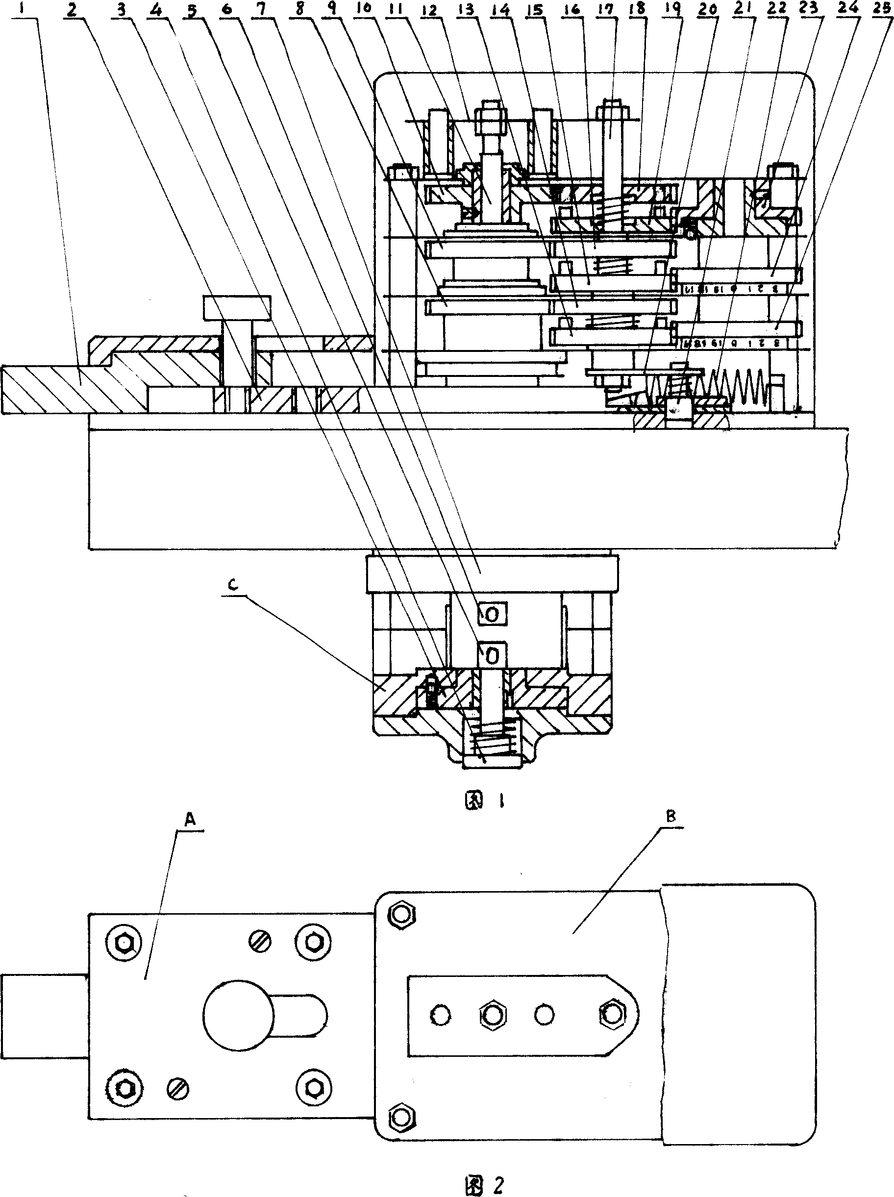
[0012] In Fig. 1, the combination lock is composed of three parts: lock body A, encoder B and encoder C. When setting the password, turn the three code-adjusting transmission gears (positioned by steel balls between the transmission gear and the splint) 25, 24, and 23 to the engraved position, and then select one of the numbers (0-19) respectively. Numbers form a set of passwords. According to the permutation and combination, there are 8001 (20 3 +1) Set of numbers to choose from. And 3 gears 13, 15, 19 for adjusting codes meshing with it, with shaft pins on the end faces, are in the password position set. As shown in Figure 1, the lock is closed. If you open the combination lock, do the following operations: According to the set password, turn the code matching handwheel in the code matching device C in sequence (the steel ball is used to position the handwheel and the machine base) 6, 5, 3, that is, through the respective sleeves. Cylinder rotates code transmission gear ...


PUM


Abstract

The present invention relates to a cryptographic lock for burglary-resisting door. Said cryptographic lock has not lock core and has not key, so that it can prevent technical unlocking burglary. Said cryptographic lock is formed from three portions of lock body, code-matching device and code-checking device. Its main technique is characterized by adopting a mechanical cryptograph identification mechanism. Said invention also provides the concrete structure of the above-mentioned every portion, and the concrete working principle of said cryptographic lock and its concrete operation method.

Description

Technical field [0001] The invention relates to a new type of lock developed for the field of anti-theft door production, in particular to a coded lock that improves the security level of the anti-theft door. Background technique [0002] In recent years, with the emergence of technology unlocking, technology theft has also occurred frequently. The anti-theft door is intact, but the residents are stolen and suffer heavy losses. Such reports are frequently seen in newspapers. At present, my country still lacks management regulations on technical unlocking, which creates worrying social problems. There are many anti-theft door manufacturers in my country, and the products they produce have various appearances. Its locks include ordinary locks, cross locks, magnetic locks and electronic locks. But, all have continued to use lock cylinder basically, the traditional marble structure of unblanking with key. This leaves a structural weakness for technical unlock theft. Conte...

Claims


Application Information

Patent Timeline
Patent Type & Authority Applications(China)
IPC IPC(8): E05B37/20
Inventor 孟昭祥
Owner 孟昭祥
Learn More