Developing device and image forming apparatus
A developing device, latent image technology, applied in the direction of electric recording process applying charge pattern, equipment for applying electric recording process of charge pattern, electric recording technique, etc. The shape and arrangement method are not uniform and scattered.
- Summary
- Abstract
- Description
- Claims
- Application Information
AI Technical Summary
Problems solved by technology
Method used
Image
Examples
no. 2 approach to no. 4 approach
[0165] [Other Embodiments (Second Embodiment to Fourth Embodiment, etc.)]
[0166] The developing device and the like according to the present invention have been described above based on the above-mentioned embodiments, but the above-mentioned embodiments of the invention are only for making the present invention easier to understand, and are not intended to limit the present invention. The present invention can be changed and improved without departing from the gist thereof, and of course equivalents thereof are also included in the present invention.
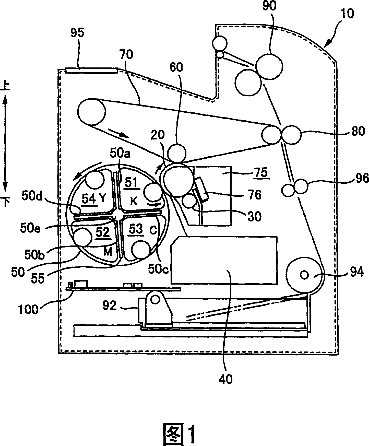
[0167] In the above-mentioned embodiments, an image forming apparatus has been described taking a full-color laser printer as an example, but the present invention can also be applied to various image forming apparatuses such as monochrome laser printers, copiers, and facsimile machines.
[0168] In addition, in the above-mentioned embodiment, the example in which the printer has a plurality of attaching and detachable parts ...
no. 2 approach
[0172] >
[0173] Here, a configuration example of the developing roller 510 of the developing device according to the second embodiment will be described with reference to FIGS. 15 to 18 . FIG. 15 is a schematic perspective view of the developing roller 510, showing the spiral first groove 1518a and the second groove 1518b with different winding directions. FIG. 16 is a schematic front view of the developing roller 510 , showing the positional relationship of the uneven processed portion 1512 , the non-embossed processed portion 1514 , and the intermediate portion 1516 of the developing roller 510 . FIG. 17 is a schematic diagram of the cross-sectional shape of the trench 1518 . FIG. 18 is a schematic cross-sectional view of A-A of FIG. 16 , showing the difference between the depth of the groove 1518 of the concave-convex processed part 1512 and the depth of the groove 1518 of the middle part 1516 . In FIGS. 15 to 18 , the scales of the grooves 1518 and the like are differe...
no. 3 approach
[0202] >
[0203] Here, a configuration example of the developing roller 510 of the developing device according to the third embodiment will be described with reference to FIGS. 19 to 22 . FIG. 19 is a schematic perspective view of the developing roller 510, showing the helical first groove 2518a and the second groove 2518b whose winding directions are different from each other. 20 is a schematic front view of the developing roller 510 showing the positional relationship between the groove-forming portion 2512 and the non-grooving-forming portion 2514 of the developing roller 510 . FIG. 21 is a schematic diagram of the cross-sectional shape of the groove 2518 . FIG. 22 is a schematic cross-sectional view of A-A of FIG. 20 , showing the difference between the depth of the groove 2518 in the central portion 2512a and the depth of the groove 2518 in the two end portions 2512b. In addition, in FIGS. 19 to 22 , the scales of the grooves 1518 and the like are different from actual...
PUM
 Abstract
Description
Claims
Application Information
 - R&D
- Intellectual Property
- Life Sciences
- Materials
- Tech Scout
- Unparalleled Data Quality
- Higher Quality Content
- 60% Fewer Hallucinations
Browse by: Latest US Patents, China's latest patents, Technical Efficacy Thesaurus, Application Domain, Technology Topic, Popular Technical Reports.
© 2025 PatSnap. All rights reserved.Legal|Privacy policy|Modern Slavery Act Transparency Statement|Sitemap|About US| Contact US: help@patsnap.com


