
Signal precoding method

A precoding and signal technology, applied in the field of signal precoding, can solve problems such as signal detection performance decline, matrix H is large, system performance reduction, etc., to achieve the effect of improving signal detection performance, reducing the probability of occurrence of singularity, and improving work performance

Inactive Publication Date: 2007-05-23
POTEVIO INFORMATION TECH
View PDF0 Cites 3 Cited by
  • Summary
  • Abstract
  • Description
  • Claims
  • Application Information

AI Technical Summary

Problems solved by technology

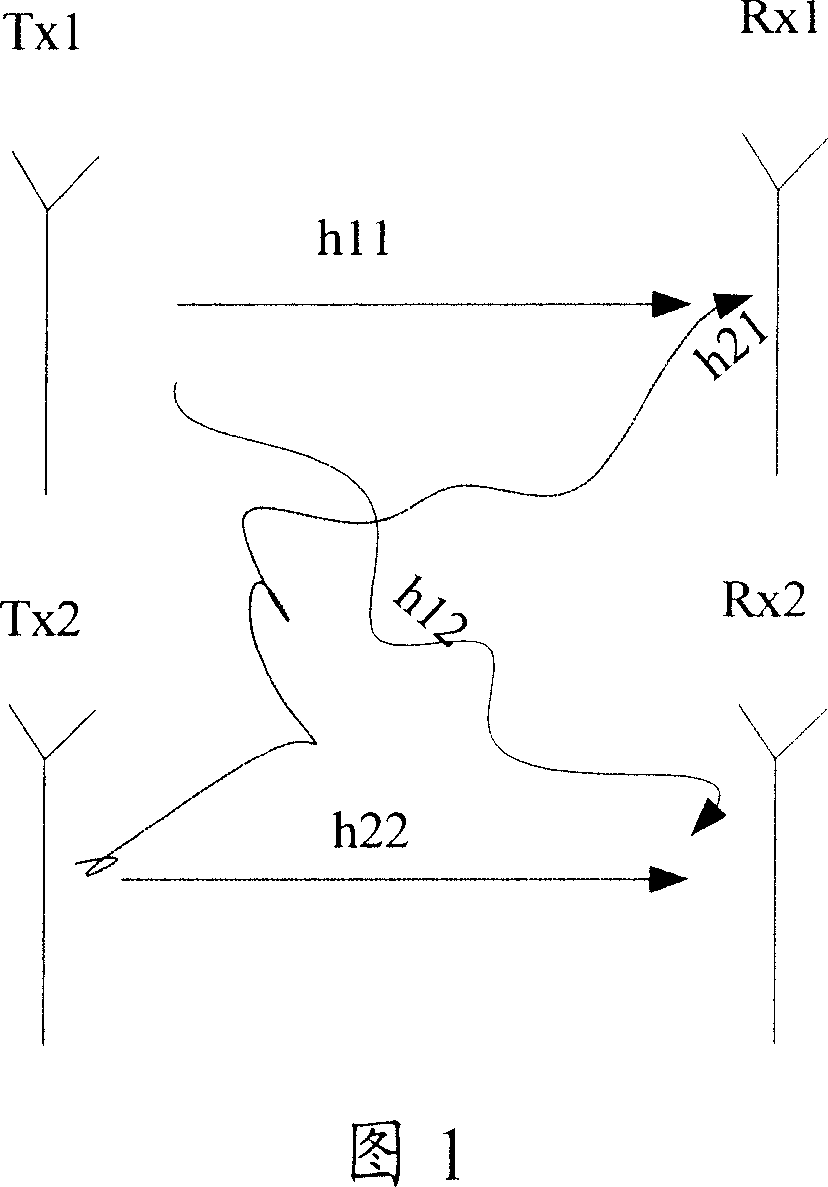
[0019] For the convenience of illustration, here it is assumed that h 11 , h 12 , h 21 , h 22 They are all 1. If there is no special explanation below, this assumption is established. It is obvious that H H H, is a singular matrix, if it cannot be solved, the weighting factor cannot be obtained, and then the transmitted signal d cannot be estimated correctly, which will seriously reduce the performance of the system
In a MIMO system, when the channel is a Gaussian channel or the correlation between the branches of the channel is strong, the matrix H H H is more likely to be singular, and in severe cases, it will cause the MIMO system to fail to detect signals normally
[0020] In fact, for other signal detection algorithms, the inversion process of a certain matrix may also be involved in the process of signal detection. If the matrix is ​​singular, the problem of signal detection performance degradation will occur.

Method used


Image

  • Signal precoding method
  • Signal precoding method
  • Signal precoding method

Examples


Embodiment

[0058] In this embodiment, it is assumed that the MIMO system shown in FIG. 1 is further a TD-SCDMA system, and its uplink and downlink traffic channels are symmetrical, so the channel matrix can be obtained.

[0059] This embodiment continues to use the received signal model shown in formula (6), and simplifies it to

[0060] y 11 y 12 y 21 y 22 = h 11 h 21 h ...


PUM


Abstract

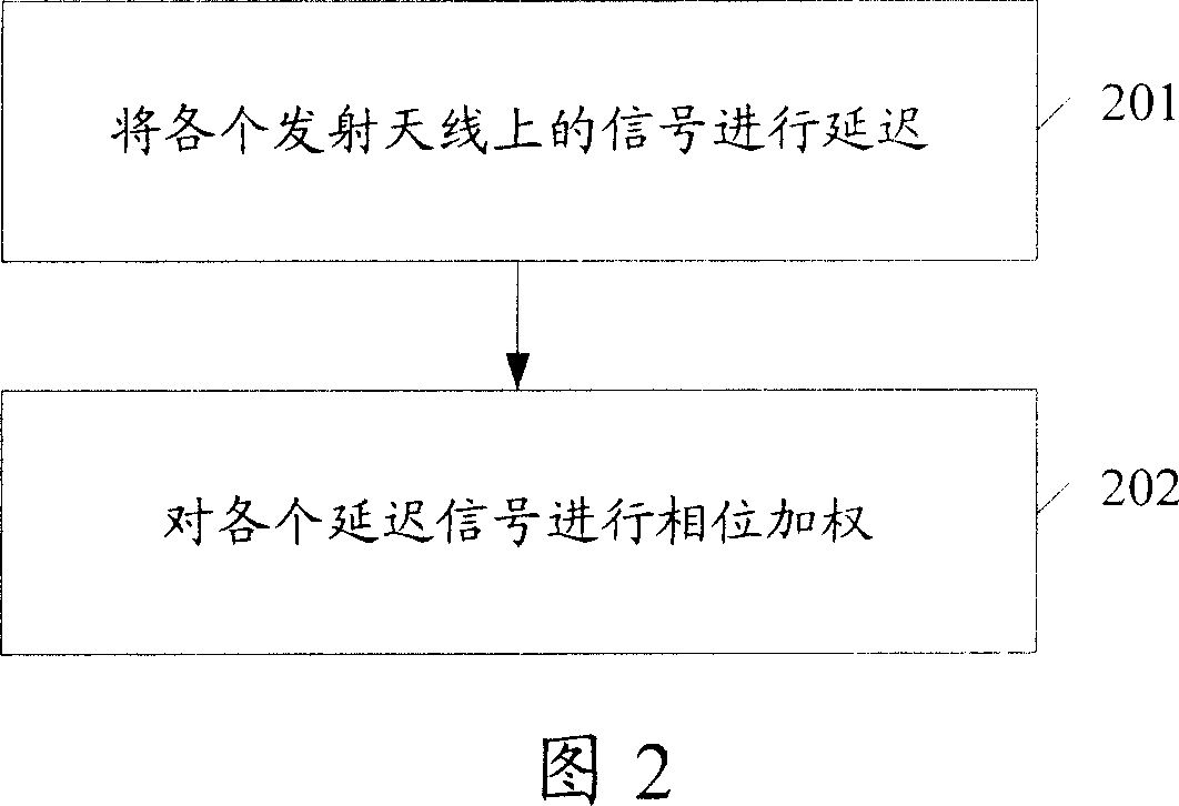
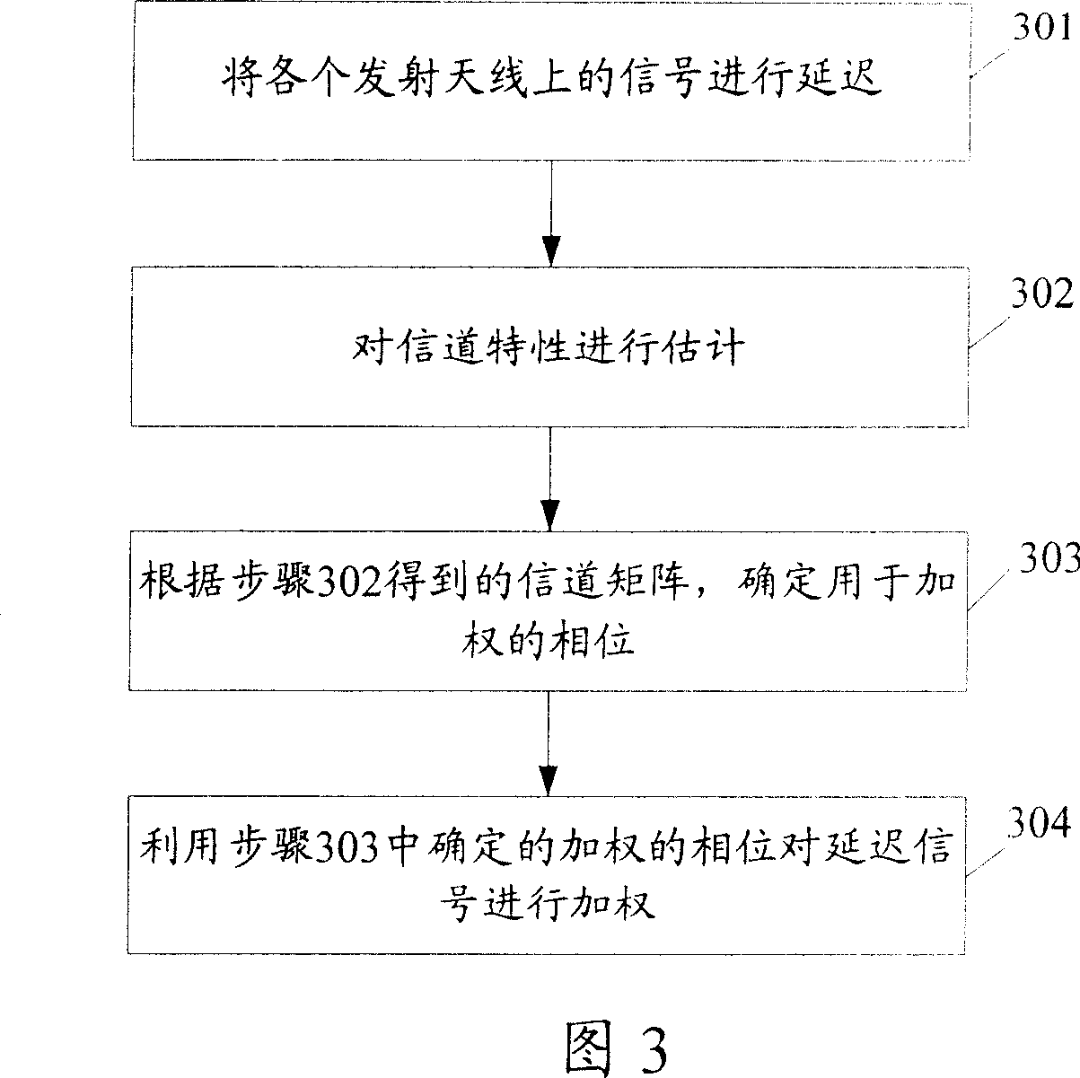
The invention relates to a signal precode method, wherein it comprises that: delaying the signal of each emission antenna; weighting phase of each delayed signal; when the precoded signal reaches receiver, checking the original signal, eliminating the weighted phase and delayed time, as changing the channel matrix; in following check, there will not be singular inverse matrix, to improve the signal checking property.

Description

technical field [0001] The invention relates to the signal transmission technology of the mobile communication system, in particular to a signal precoding method. Background technique [0002] In the mobile communication system, the sending end sends various signals. After the signal reaches the receiving end through the wireless channel, some changes may occur. The receiving end uses a certain algorithm to restore the received signal to the sending signal process, which is called Signal Detection. [0003] Suppose the signal received by the receiver is Y=Hd+n (1) [0004] Among them, A is the channel matrix, indicating the channel characteristics of the transmitted signal during transmission, d is the transmitted signal, indicating the actual information of the transmitting end, and n is the channel noise. When the receiving end performs signal detection, the usual method is: first obtain the weighting factor W, and then estimate the transmitted signal according to Y=Wd. ...

Claims


Application Information

Patent Timeline
IPC IPC(8): H04L1/00H04L1/06
Inventor 程型清
Owner POTEVIO INFORMATION TECH
Learn More