Electric vacuum cleaner

A vacuum cleaner and electric technology, which is applied in the installation of suction nozzles and electrical equipment, etc., can solve the problems of no dust being detected, no display of the vacuum cleaner, and inability to know whether the vacuum cleaner is in a normal state or in a fault state.

Inactive Publication Date: 2007-06-06
PANASONIC CORP
View PDF1 Cites 9 Cited by
  • Summary
  • Abstract
  • Description
  • Claims
  • Application Information

AI Technical Summary

Problems solved by technology

[0003] However, if the above-mentioned existing device structure is adopted, after the user starts vacuuming, if the ground is clean, since there is no dust passing through, no dust will be detected in the dust detection device 112.
Even if such a state lasts only for a dozen seconds, the user will feel uneasy about the indicator light not being on, and may suspect that the vacuum cleaner is malfunctioning.
[0004] In addition, in a common vacuum cleaner, after the power plug is inserted into the socket, the vacuum cleaner does not display whether it is in a ready state. Normal state, or is it in a faulty state

Method used


Image

  • Electric vacuum cleaner
  • Electric vacuum cleaner
  • Electric vacuum cleaner

Examples


Embodiment 1

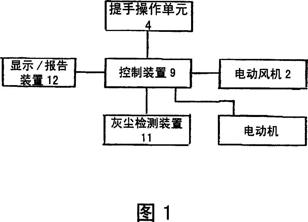
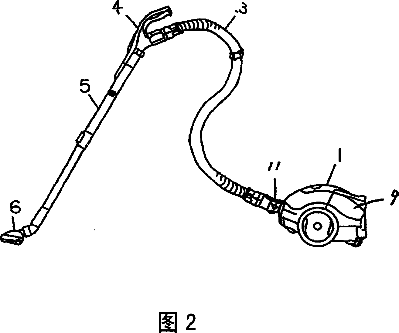
[0022] Fig. 1 is a circuit block diagram of an electric vacuum cleaner in the first embodiment of the present invention, and Fig. 2 is a schematic diagram of the appearance of the electric vacuum cleaner.

[0023] In Fig. 2, 1 is the body of the electric vacuum cleaner, which is equipped with an electric fan 2 for generating suction and collecting dust into the dust collection chamber (not shown in the figure). 3 is the handle operation unit 4 and the body of the vacuum cleaner 1 connected hose, the handle operating unit 4 is provided with operation switches (operating positions) such as "strong", "automatic" and "weak", which can switch the strength of attraction of the electric fan 2. 6 is the suction head that contacts with the ground, thereby the dust etc. on the surface to be cleaned are sucked up, and the inside of the suction head 6 is provided with a rotating brush (not shown) for sweeping up the dust on the surface to be cleaned and A rotating brush motor (not shown i...

Embodiment 2

[0036] Fig. 7 is a schematic diagram showing an example of the handle operation unit 4 and the display / report device 12 in the second embodiment of the present invention. Here, the same parts as those in the above-mentioned first embodiment are given the same symbols, and their descriptions are omitted.

[0037] As shown in FIG. 7, when there is no signal input in the dust detection device 11, the display / reporting device 12 is usually in an off state, and if the dust detection device 11 detects dust, it displays in different states such as lighting. In the vacuum cleaner of the present invention, when the phase is at 550W, the current detection device 14 detects the air volume through the current flowing through the electric fan 2 . When detecting and judging the air volume, considering factors such as the stability of the current change, it is best to perform detection for about 5 seconds. Within these 5 seconds, if there is a signal output from the dust detection device 11...


PUM


Abstract

The present invention provides an electromotion cleaner with easily operation which can tell user whether the display / report device for reporting the existence of dust is in normal or not. The cleaner comprises a handle operation unit (operation assembly) 4 for drive the electromotion fan which provides suction force, a dust detecting device 11 capable of detecting the existence of dust, a control device 9 switching the suction force of the fan in several degrees by receiving the signal from the dust detecting device, and a display / report device 12 which receives signal from the dust detecting device and then on which the information can be displayed / reported. When user turns on the cleaner by using the handle operation unit after electrifying, the signal coming from the control device and dust detecting device makes the display / report device work for a while irrespectively. Then user can know whether the display / report device is working in normal before cleaning work.

Description

technical field [0001] The present invention relates to an electric vacuum cleaner, and more particularly to a control device in which dust is detected, displayed / reported. Background technique [0002] A conventional electric vacuum cleaner is shown in Japanese Patent Laid-Open Publication No. 2002-248070. As shown in FIG. 2 , an electric blower 2 and a control device 9 with a signal processing unit are arranged inside the vacuum cleaner body 1 . The above-mentioned electric vacuum cleaner is also provided with: a hose 3 connecting the handle operation unit 4 and the vacuum cleaner body 1; a motor (not shown) arranged inside the suction head 6; driven by the motor to rotate so that the A rotating brush for sweeping up dust; and an extension tube 5 for connecting the suction head 6 and the handle operation unit 4 . The suction force of the electric blower 2 and the rotation / stopping of the motor can be controlled through the handle operation unit 4 . As shown in Figure 7,...

Claims


Application Information

Patent Timeline
Patent Type & Authority Applications(China)
IPC IPC(8): A47L9/28A47L9/04
Inventor 上野圣一曾根健次妹尾裕之
Owner PANASONIC CORP
Why Eureka
Try Eureka