Connector

a technology of connecting rods and connectors, applied in the direction of incorrect coupling prevention, coupling device connection, electrical equipment, etc., can solve the problems of prior art technology not accommodating inspection from the front, the operator may not be able to see the lock hole, and the connected state of the housing cannot be detected. , to achieve the effect of improving the efficiency of operation

Inactive Publication Date: 2005-07-21
SUMITOMO WIRING SYST LTD
View PDF4 Cites 5 Cited by
  • Summary
  • Abstract
  • Description
  • Claims
  • Application Information

AI Technical Summary

Benefits of technology

[0010] The invention relates to a connector with first and second housings that are connectable with each other. The first housing has a forwardly open receptacle for receiving the second housing. At least one lock is formed on an inner surface of the receptacle, and at least one receiving portion is formed on an outer surface of the second housing for engaging the lock. The lock is hidden at least partly behind the receiving portion when viewed from the front

Problems solved by technology

Thus, an operator may not be able to see the lock hole from above and the connected state of the housings cannot be detected.
However, the front surface of the receptacle is a connection surface with the female housing, and the prior art technolog

Method used


Image

  • Connector
  • Connector
  • Connector

Examples


first embodiment

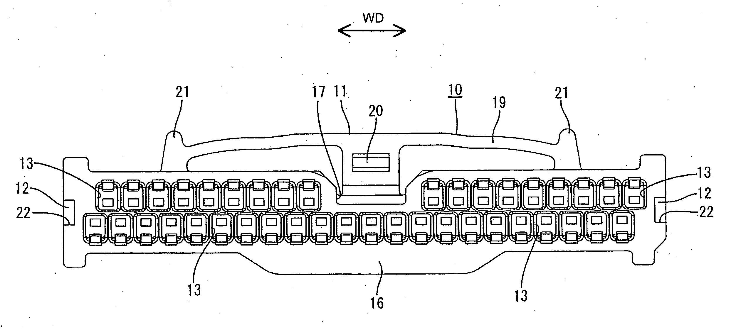
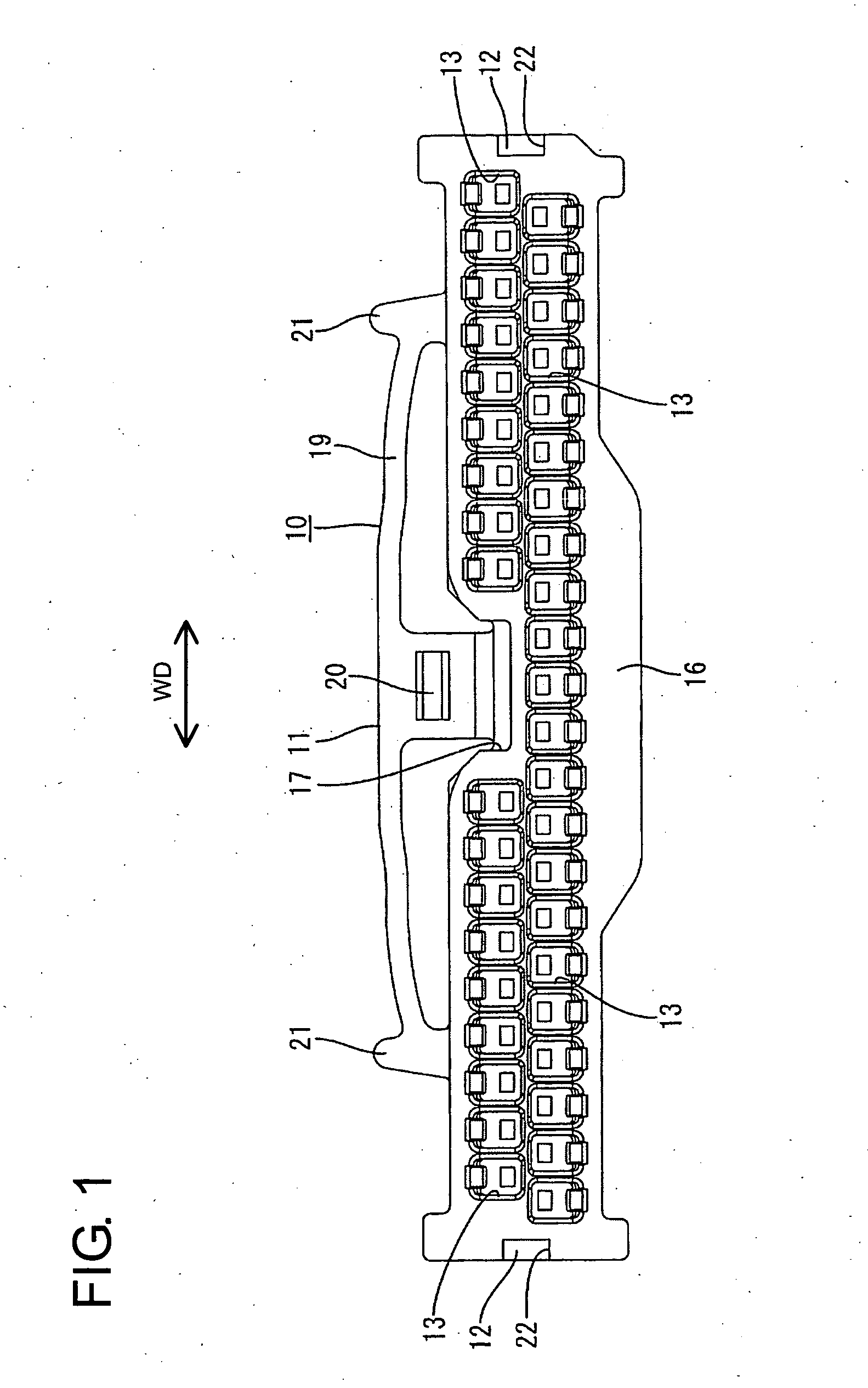
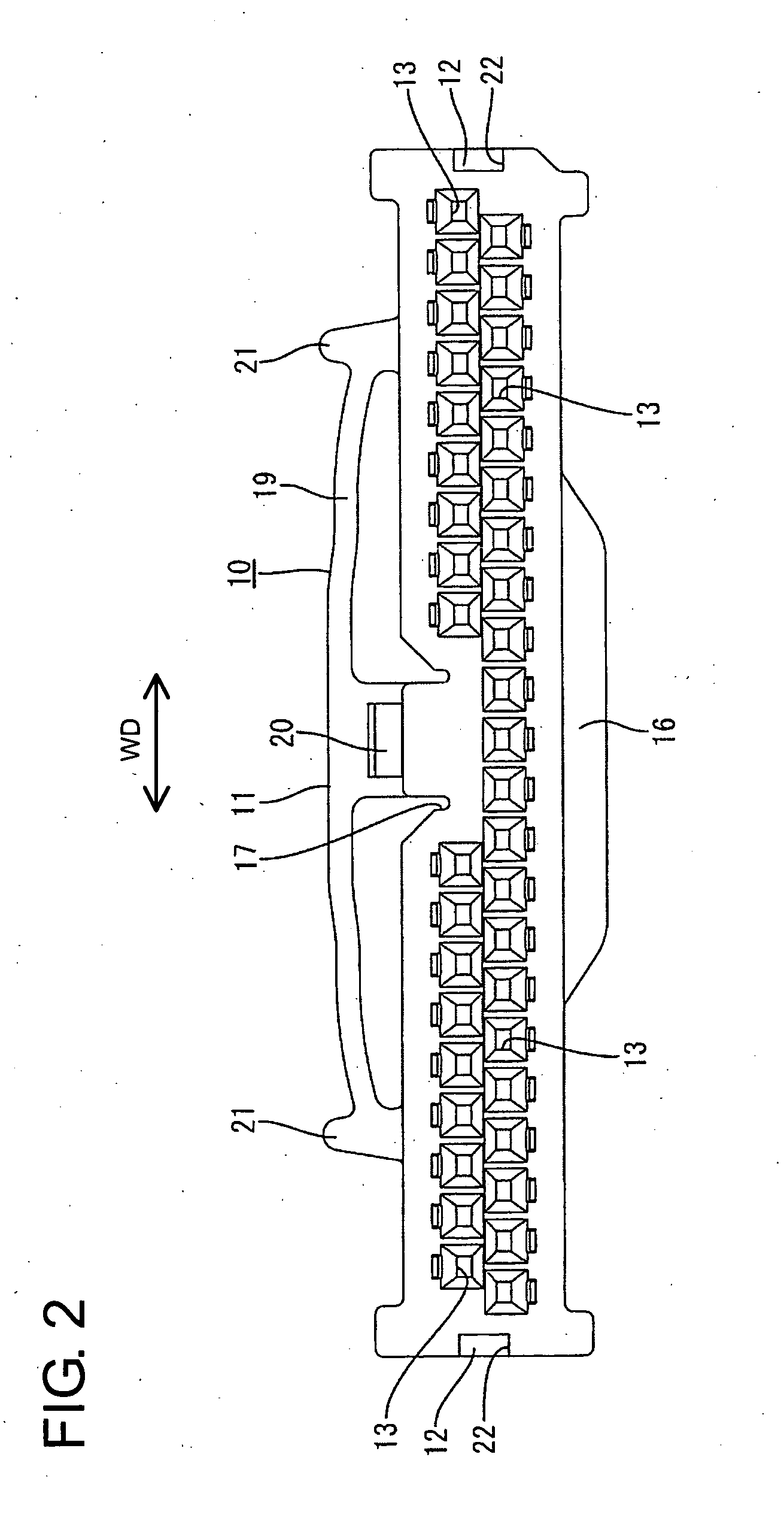
[0078] the invention is described with reference to FIGS. 1 to 14. A connector of this embodiment has female and male housings 10, 40 connectable with each other. The female housing 10 is wide block made e.g. of a synthetic resin. Cavities 13 penetrate the female housing 10 in forward and backward directions FBD and female terminal fittings 80 are insertable into the cavities 13 from behind, as shown in FIG. 12. Each female terminal fitting 80 has a known construction, and includes a rectangular tubular main portion 81 that is hollow in forward and backward directions FBD. A barrel 82 is formed behind the main portion 81 and is crimped into connection with an end of a wire W. A contact piece 83 is formed in or at the main portion 81 and can be brought resiliently into contact with a male terminal fitting 90. As shown in FIGS. 1 and 2, the cavities 13 are arranged at upper and lower stages, with those at the upper stage offset from those at the lower stage.

[0079] A U-shaped slit 14 i...

second embodiment

[0101] The fixing member 47 of the second embodiment is mounted onto the male housing 40 from above and along the mounting direction MD. Thus, the inclined surfaces of lower guides 42E slide along the opposite widthwise edges of the upper surface of the male housing 40. Accordingly, the locks 42A are guided through outward resilient deformations, and the fixing member 47 is mounted smoothly. On the other hand, the inclined surfaces of the upper guides 42E slide along the edges of the mount holes 52A when the fixing member 47 is separated upwardly from the male housing 40, and the locks 42A are guided through outward resilient deformations. Thus, the fixing member 47 also can be separated smoothly.

[0102] A third embodiment of the invention is described with reference to FIGS. 18 to 32. A connector of this embodiment has female and male housings 110, 140 connectable with each other along a connecting direction CD and a wire cover 160 rotatably mounted on the female housing 110. As sho...

fourth embodiment

[0129] A locking construction for the wire cover 160 of the fourth embodiment is provided on the female housing 110. More specifically, as shown in FIG. 33, the female housing 110 has two engaging portions 130 that bulge out from the opposite upper and lower ends of the rear end edge of one side surface. Guiding surfaces 130A are formed at the front surfaces of engaging portions 130.

[0130] As shown in FIG. 34, locking sections 161 project forward from the front end edge of the wire cover 160 near the other end, and are shorter than and substantially in parallel to the partial locks 163. A locking protuberance 173 projects in from the projecting end of each lock 161, and has a guidable surface 173A for sliding contact with a corresponding guiding surface 130A of the corresponding engageable section 149 as shown in FIG. 35.

[0131] Projecting pieces 177 project forward from the front end edge of the wire cover 160. The projecting pieces 177 are wider than the partial locks 163 and shor...


PUM


Abstract

Upon fitting a female housing (10) into a receptacle (44) of a male housing (40), metallic lock portions (42) are hidden behind receiving portions (12) when viewed from the front side of the receptacle (44) at an initial stage. When the lock portions (42) move over the receiving portions (12) while being resiliently deformed as this fitting operation progresses, the lock portions (42) are engaged with the receiving portions (12) and can be visually confirmed from the front side of the receptacle (44). Thus, the properly connected state of the two housings (10, 40) can be detected by visually confirming the lock portions (42) from the front side of the receptacle (44).

Description

BACKGROUND OF THE INVENTION [0001] 1. Field of the Invention [0002] The present invention relates to a connector. [0003] 2. Description of the Related Art [0004] Japanese Unexamined Patent Publication No. 2002-216901 discloses a connector with male and female housing that are connectable with each other. The male housing is formed with a receptacle to surround male terminal fittings and a lock hole penetrates the upper wall of the receptacle. The female housing has a lock projection that is engageable with the lock hole. The receptacle is deformed resiliently outward in the process of connecting the two housings to permit insertion of the lock projection into the receptacle. The receptacle is restored resiliently to its initial position when the housings are connected properly connected. Thus, the lock projection engages in the lock hole to lock the two housings together. [0005] Engagement of the lock projection in the lock hole can be confirmed visually when the lock hole is seen f...

Claims


Application Information

Patent Timeline
IPC IPC(8): H01R13/627H01R13/629H01R13/64H01R13/641
CPCH01R13/641H01R13/6272H01R13/629H01R13/64
Inventor MATSUNAGA, HIDEKI
Owner SUMITOMO WIRING SYST LTD
Why Eureka
Try Eureka