Latch-mountable connector housing, latch-mountable conector, and electric connecting device

a technology of latch-mounting connectors and connector housings, which is applied in the direction of connection, electrical apparatus, and connection, etc., can solve the problems of not being able to achieve clear clicking feel at the time of connecting, exposed center portion of metal latches, etc., and achieves the effect of simple structure and convenient unlocking operation

Active Publication Date: 2009-04-30
JST MFG CO LTD
View PDF7 Cites 5 Cited by
  • Summary
  • Abstract
  • Description
  • Claims
  • Application Information

AI Technical Summary

Benefits of technology

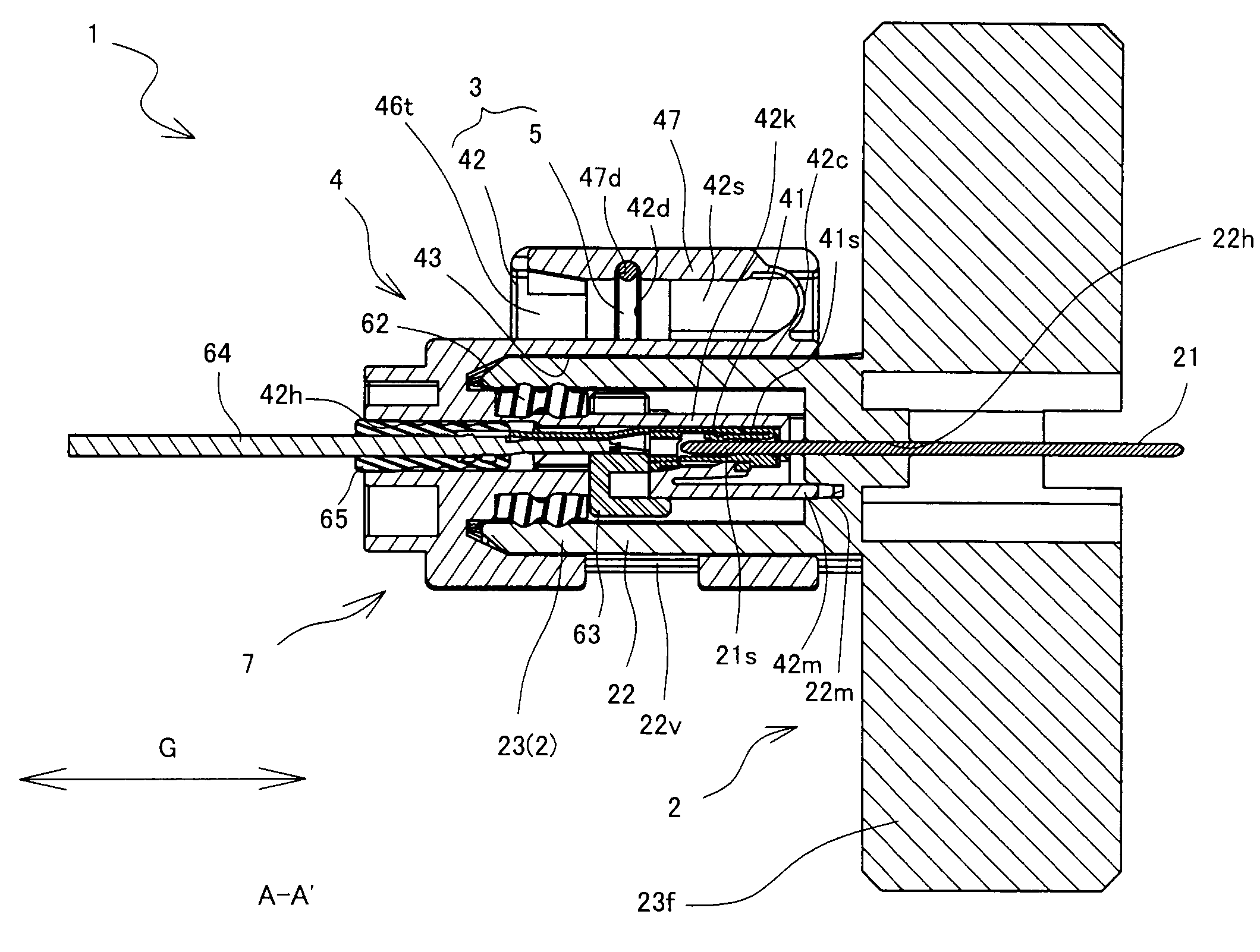
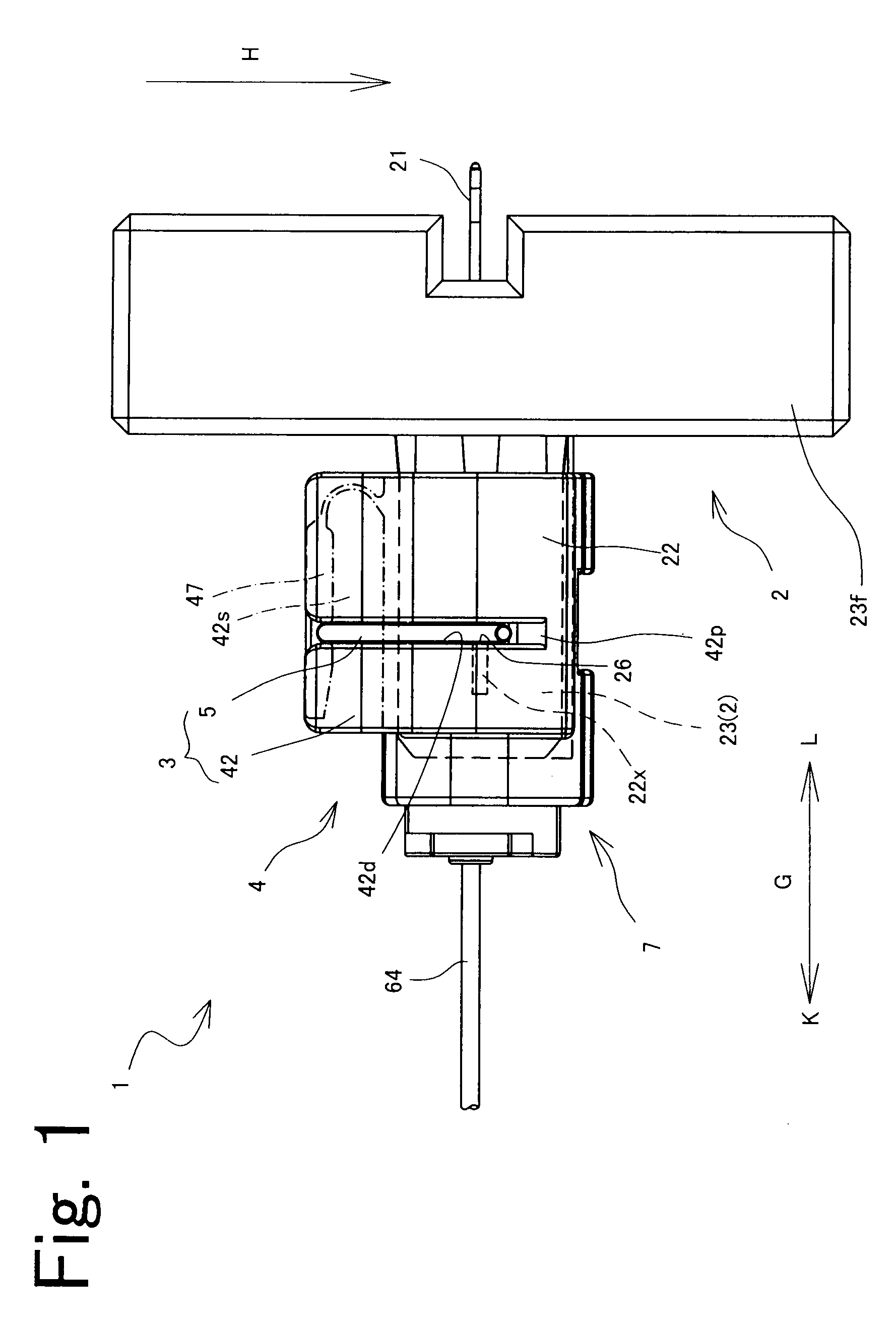
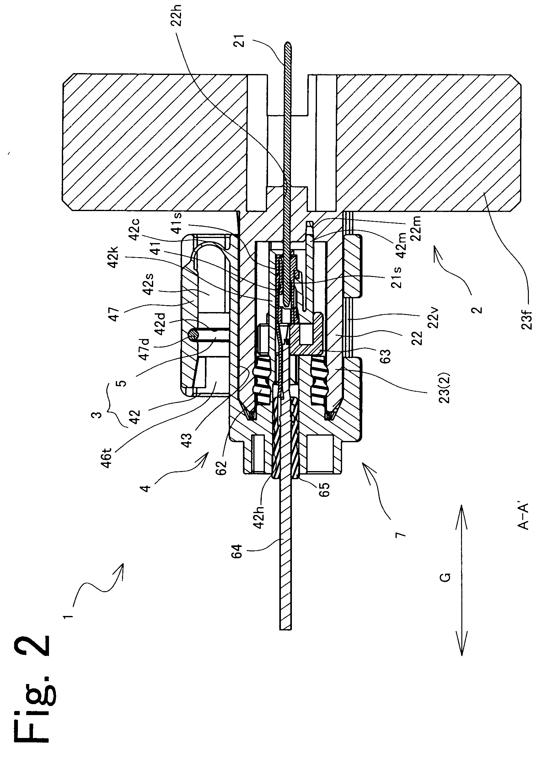
[0010]In the structure, the pair of connectors are connected to each other, and the both connector terminals are electrically connected during the connected state. The latch which sandwiching and supporting the counterpart housing serves to inhibit separation of the pair of connectors from each other. Further, the latch has a pair of support portions which are latched on the pair of support receivers formed on the counterpart housing during the connected state of the pair of connectors. The latch once having been deformed with a movement of connecting the pair of connectors resiliently restore its original state, thereby yielding a clicking feel. Further, in the structure, the connector housing has the grooves for mounting thereon the latch, and the cover for covering the latch. The latch therefore is kept from being pressed by a finger. Thus, a clear clicking feel is obtained at the time of connection, enabling reliable confirmation of connection, irrespective of how the connector housing is held. The above structure is simple, and yet allows reliable confirmation of connection.
[0022]The electric connecting device of the present invention may be adapted so that: the cover is formed in a plate-like shape; the latch is mounted in a direction perpendicular to the connecting direction, so as to be positioned on a plane perpendicular to the connecting direction of the second housing to the first housing; an unlocking sloping surface is formed on the front side of each groove on the second housing, relative to the mounting direction of the latch; and when the cover is pressed while the latch is in the mounting position and the support portions of the latch are latched on the support receivers respectively, the latch is further pressed towards the front side relative to the mounting direction, and each unlocking sloping surface contacts the support portion, thus outwardly spreading the support portions. With this, the cover ensures a clicking feel at the time of connection, and allows easier unlocking operation.

Problems solved by technology

However, while the metal latch is mounted on the female housing of the electric connector of the above publication, at least the center portion of the metal latch is exposed and is not accommodated in the housing.
When the metal latch is exposed as in the above electric connector, a clear clicking feel at the time of connecting may not be achieved depending on how the connector is held.
However, pressing a part of the metal latch by a finger restrains the connecting sound or the connecting feel given by the metal latch at the time of connection.

Method used


Image

  • Latch-mountable connector housing, latch-mountable conector, and electric connecting device
  • Latch-mountable connector housing, latch-mountable conector, and electric connecting device
  • Latch-mountable connector housing, latch-mountable conector, and electric connecting device

Examples


embodiment 2

[0142]Next, the electric connecting device of Embodiment 2, according to the present invention is described below, mainly focusing on the difference from the above embodiment. Note that the members that are similar to those of the above embodiment are given the same reference symbols and no further explanation is provided hereinbelow. Further, in the present embodiment, members and parts given the reference symbols 303, 305, 321, 321s, 322, 322f, 322s, 322v, 322w, 322x, 323, 323s, 324, 325, 326, 341, 342, 342h, 342t, 346, 347, 347d, 347t, 364, and 365 respectively correspond to the members and parts of the foregoing embodiment given the reference symbols 3, 5, 21, 21s, 22, 22f, 22s, 22v, 22w, 22x, 23, 23s, 24, 25, 26, 41, 42, 42h, 42t, 46, 47, 47d, 47t, 64, and 65. The respective functions of these members and parts are the same as the foregoing embodiment. FIG. 13 is an exploded perspective view illustrating members constituting an electric connecting device of Embodiment 2, accord...

embodiment 3

[0145]Next, the electric connecting device of Embodiment 3 according to the present invention is described below, mainly focusing on the difference from the above embodiment. Note that the members that are similar to those of the above embodiment are given the same reference symbols and no further explanation is provided hereinbelow. Further, in the present embodiment, members and parts given the reference symbols 403, 405, 422, 422f, 422s, 422v, 422w, 422x, 423, 423s, 424, 425, 426, 441, 442, 442h, 442t, 446, 447, 447d, 447t, 464, and 465 respectively correspond to the members and parts of the foregoing embodiment given the reference symbols 3, 5, 21, 21s, 22, 22f, 22s, 22v, 22w, 22x, 23, 23s, 24, 25, 26, 41, 42, 42h, 42t, 46, 47, 47d, 47t, 64, and 65. The respective functions of these members and parts are the same as the foregoing embodiment. FIG. 14 is an exploded perspective view illustrating members constituting an electric connecting device of Embodiment 3 according to the pr...


PUM


Abstract

A metal-latch-mountable connector housing 3 includes: a main body 42b; and a metal latch 5 which is capable of resiliently sandwiching a first housing 22 so as to inhibit separation of the main body 42 and the first housing 22 from each other. During a connected state, the metal latch 5 sandwiches the first housing 22 between a pair of support portions 51, and the support portions 51 are respectively latched on a pair of support receivers 26. The metal-latch-mountable connector housing 3 further has a groove 42d for mounting thereon the metal latch 5, and a cover 47 for covering the metal latch 5.

Description

CROSS REFERENCE TO RELATED APPLICATION[0001]The present application claims priority from Japanese Patent Application No. 2007-276604, which was filed on Oct. 24, 2007, the disclosure of which is herein incorporated by reference in its entirety.BACKGROUND OF THE INVENTION[0002]1. Field of the Invention[0003]The present invention relates to a latch-mountable connector housing, a latch-mountable connector, and an electric connecting device, each of which enables reliable confirmation of connection.[0004]2. Description of Related Art[0005]Japanese Unexamined Patent Publication No. 2006-202557 (Tokukai 2006-202557; hereinafter Patent Document 1) discloses an example of known electric connector. In the electric connector, a metal latch, while being supported in a guide groove of a female housing, applies a preload to the female housing and a male housing, in a direction of fitting these housings with each other. A metal latch provided at a spring part of the metal latch fits in a fixing g...

Claims


Application Information

Patent Timeline
Patent Type & Authority Applications(United States)
IPC IPC(8): H01R13/627
CPCH01R13/6277
Inventor NAGAMINE, AKIRA
Owner JST MFG CO LTD
Why Eureka
Try Eureka