Speed control method of continuous processing apparatus

A speed control and processing equipment technology, which is applied in heat treatment equipment, heat treatment process control, roll speed control, etc., can solve the problem that the setting of the moving speed of the rolled material depends on the operation of the operator, etc.

A speed control and processing equipment technology, which is applied in heat treatment equipment, heat treatment process control, roll speed control, etc., can solve the problem that the setting of the moving speed of the rolled material depends on the operation of the operator, etc.

CN1974038AInactive Publication Date: 2007-06-06HITACHI LTD

Image

  • Speed control method of continuous processing apparatus
  • Speed control method of continuous processing apparatus
  • Speed control method of continuous processing apparatus

Examples


Embodiment Construction

[0039] Hereinafter, the rolling speed control device of the continuous rolling facility of the present invention will be described in detail with reference to the illustrated embodiments.

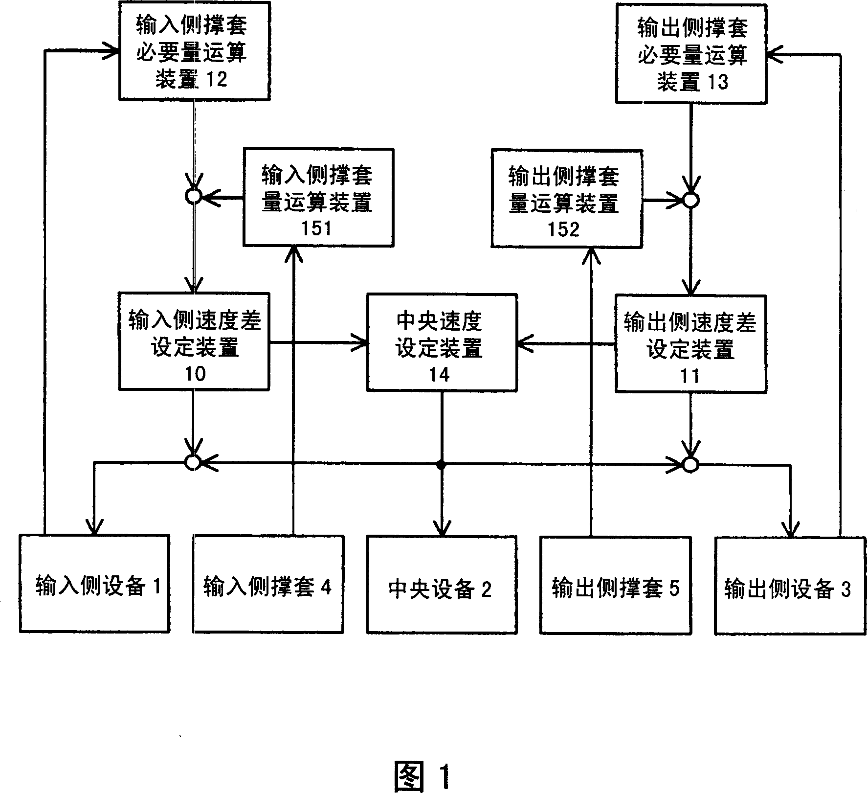
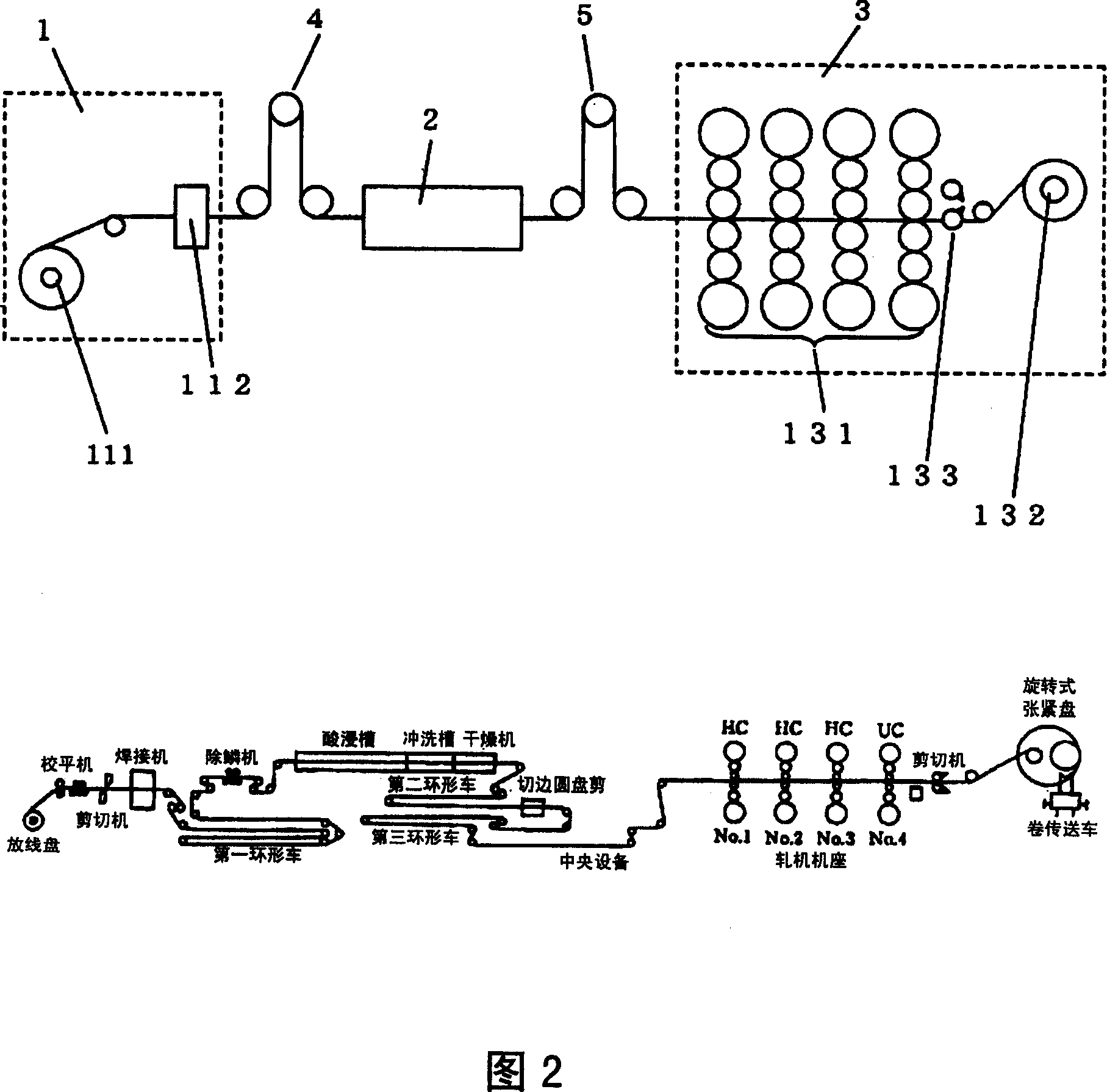
[0040] Fig. 1 is an embodiment of the present invention, which is an embodiment when the present invention is applied to the continuous rolling equipment shown in Fig. 2, therefore, in Fig. , Input side support sleeve 4, output side support sleeve 5, same as the situation of Fig. 2.

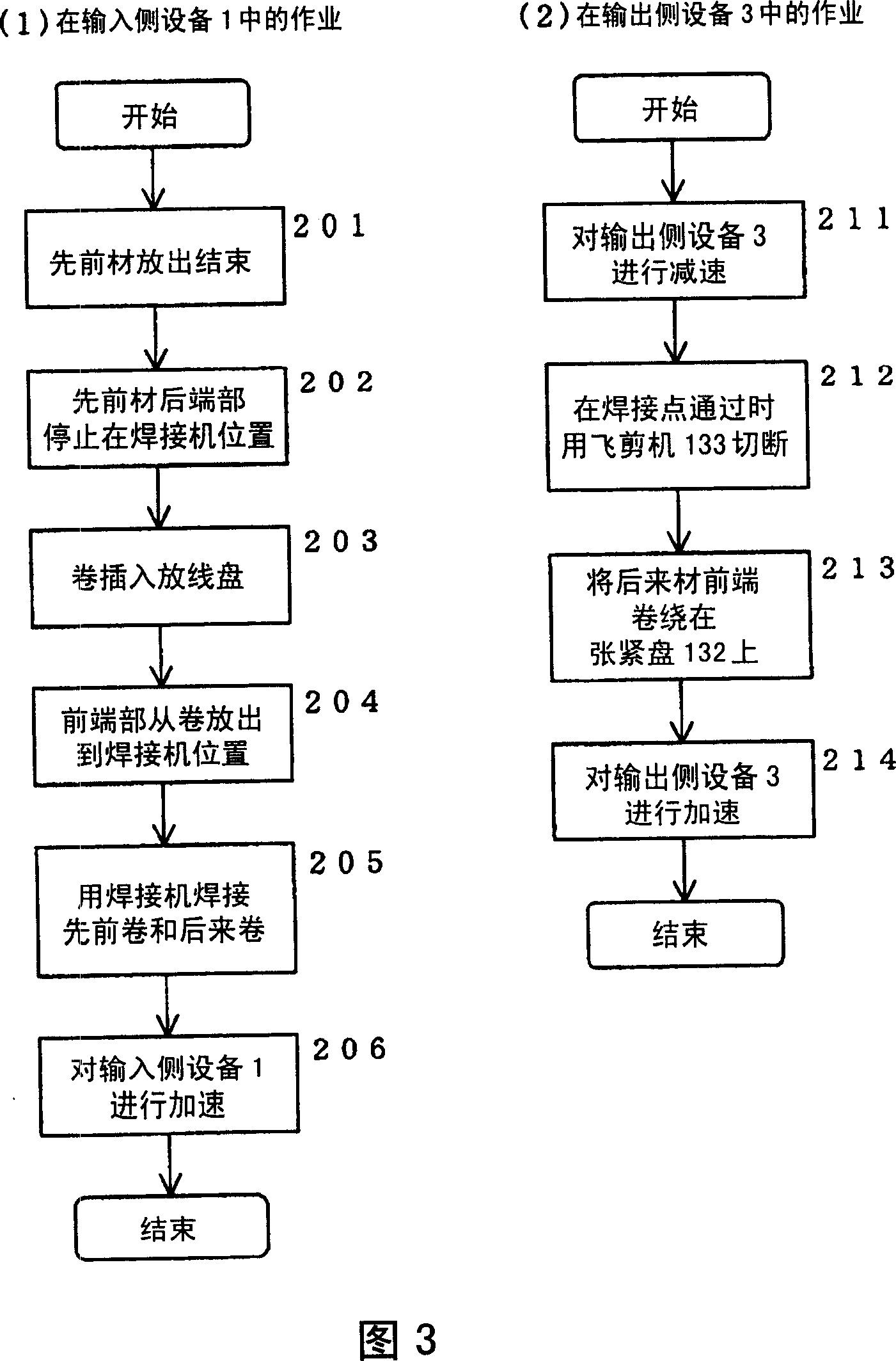
[0041] Therefore, as shown in FIG. 2, the input side equipment 1 is equipped with the pay-off reel 11, the welding machine 112, and these incidental equipment. In addition, the input-side facility 1 needs to perform operations shown in FIG. 3( 1 ) during facility operations in order to continuously supply the rolled material.

[0042] First, if one volume of rolled material is pulled out, the next rolled material is inserted into the pay-off reel 111, and the next rolled material is welded to the rear end of ...


PUM


Abstract

The invention provides a speed control method for continuous processing equipment capable of automatically arranging the transfer speed of the processing material. A continuous rolling apparatus has an input support sleeve 4 between an input device 1 and a central device 2, and an output support sleeve 5 between the central device 2 and an output device 3, wherein according to the operation state of the input device 1 and the output device 3, the necessary value of the input support sleeve 4 and that of the output support sleeve 5 can be obtained, and the speed difference between the input device 1 and the central device 2 and that between the central device 2 and the output device 3 are arranged, then the speed of each part can be controlled and the cumulating value of each support sleeve is converted to a necessary value.

Description

technical field [0001] The present invention relates to a control method of equipment for continuously processing processed materials, and in particular to a speed control method suitable for controlling the rolling speed of continuous rolling equipment with coiled thin plates as rolled materials. Background technique [0002] As one type of equipment for continuously processing the material to be processed, there is a continuous rolling equipment for thin plate materials such as steel strips wound into coils. In such continuous rolling equipment, in order to continuously process the material to be rolled, usually It is divided into input side equipment, central equipment and output side equipment. [0003] Therefore, an example of such a continuous rolling device will be described with reference to FIG. 2 . In addition, an example of an actual machine of such a continuous rolling facility is shown as a reference example on the lower side of FIG. 2 . [0004] In FIG. 2 , f...

Claims


Application Information

Patent Timeline
06 Jun 2007
Publication
CN1974038A
IPC
B21B37/00; B21B41/00; B21C49/00; B21B37/46; C21D11/00; C21D9/52; C23G3/02; B65H23/188
CPC
B21B37/005; B21B37/46; B21B37/72; B21B2275/02; B21B2275/06
Inventors
服部哲; 福地裕