Method for metering reactive electric energy

A measurement method and technology of electric energy, which is applied in the measurement of electric variables, electric power measurement through current/voltage, and electrical devices, etc., and can solve problems such as incorrect or insufficient reactive energy measurement methods, and inability to fully meet the requirements

Inactive Publication Date: 2007-06-06
WUHAN UNIV
View PDF0 Cites 7 Cited by
  • Summary
  • Abstract
  • Description
  • Claims
  • Application Information

AI Technical Summary

Problems solved by technology

[0021] However, the existing power systems cannot fully meet the above requirements.
Therefore, there are errors or deficiencies in the reactive energy measurement methods based on various existing power systems

Method used


Image

  • Method for metering reactive electric energy
  • Method for metering reactive electric energy
  • Method for metering reactive electric energy

Examples


Embodiment Construction

[0165] The present invention comprises the following steps:

[0166] (1) Data collection to obtain voltage and current signals at the load end

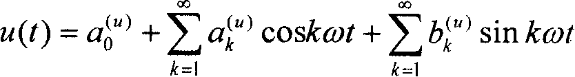
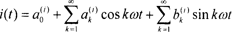
[0167] Transform the voltage and current signals at the load end into a low level that can be collected and measured through the voltage and current transmitters. If it is a three-phase load, send the voltage and current signals of each of the three phases to the voltage and current conversion Transformer, the transformed voltage and current signals are sampled synchronously and uniformly, and the number of sampling points in one power frequency cycle is N, where N≥50 and For example, take N=1024 to get the voltage sequence {u in the time domain (n)} and the current sequence {i (n)}, where 0≤n≤N-1, the Fourier expressions of the voltage and current signals transformed by the transmitter are

[0168] u ( t ) = a 0 ...


PUM


Abstract

The invention relates to a computation method of reactive electric energy. It includes the processes: the data collection of the voltage and the current signal of load side; work out the virtual value of load reactive power; get the reactive electric energy cost of the load in some time; work out the whole reactive electric energy cost of the load; repeat the above four processes. It avoids the error of the reactive electric energy in non-sine condition. According to the rule of switching without lose between the electric energy, magnetic energy and the electromagnetic energy; the three energies is constant in switching, so it is proper for the voltage and the current condition in random period waveform.

Description

technical field [0001] The invention relates to a method for measuring reactive electric energy of an AC non-sinusoidal periodic circuit. Background technique [0002] When the world's first complete DC power system was applied on Pearl Street in New York City in 1882, the concept of reactive power was not proposed by the electrical engineering community at that time. It was not until 1886, when William Stanley developed and tested the world's first practical AC power supply system at Great Barrington, that the power phenomenon in AC circuits attracted the attention of the electrotechnical community. In 1888, it was noticed that in an AC circuit, the exchange of power between the source and the load is due to the phase angle difference between the voltage and the current. William Stanley and O.B.Shallenberger respectively analyzed this phenomenon and gave physical explanation and mathematical model. The power system they proposed is the power system in the AC circuit under...

Claims


Application Information

Patent Timeline
Patent Type & Authority Applications(China)
IPC IPC(8): G01R11/52G01R21/00G01R21/06
Inventor 陈允平樊友平查晓明彭辉张茂松
Owner WUHAN UNIV
Why Eureka
Try Eureka