Implantable device for utilization of the hydraulic energy of the heart

a technology of hydraulic energy and implantable devices, which is applied in the direction of prosthesis, wound drains, therapy, etc., can solve the problems of limiting the degree of freedom of patients to special rooms or trolleys equipped with batteries and computers, affecting the patient's health, and affecting the patient's life, so as to achieve the effect of reducing the risk of strok

Inactive Publication Date: 2004-12-07
BUGGE MOGENS +1
View PDF12 Cites 70 Cited by
  • Summary
  • Abstract
  • Description
  • Claims
  • Application Information

AI Technical Summary

Benefits of technology

As mentioned, the energy absorbed from the heart by the motor may be used for several purposes. One example is to lead back the energy directly to the circulation--or later, at the same time as electricity is generated and stored in an accumulator. Arranged in this way, the net amount of energy transferred to the circulation will be the same, less or more than before connection to the motor. The profile of the blood pressure can be manipulated and the mean blood pressure can be increased.
It is even possible with this device to take out a maximum of blood volume from the ventricle at a pressure so low that the valve between the ventricle and the circulation never opens, which normally is inconsistent with life, and still absorb energy at this low pressure. The device may give back the energy to the circulation and thereby generate a sufficiently high pressure to guarantee life --without adding energy from the surrounding.

Problems solved by technology

But it may cause discomfort and be complicated for the patient due to tubings and cables penetrating the skin.
Such connections limit the patient's degree of freedom to special rooms or to trolleys equipped with batteries and computers.
When the heart is fainting, and for some reason or another cannot generate a sufficiently high blood pressure, the person will die.
The fact that the heart sometimes cannot pump out the blood to the circulation with a sufficiently high pressure does not necessarily mean that the heart cannot deliver enough energy to the circulation, if mechanical, and other conditions, were correct.
A normal heart has a relatively low efficiency as a pump, compared to industrial pumps.
This contraction leads to energy losses, which are proportional to the diameter of the ventricles in square, and therefore, these losses are great when the ventricles are dilated.
This remodeling of the muscle mass also leads to energy losses which in some diseases (for example at extremely hypertrophic hearts) may be considerable.
In contrast, energy is lost since the ventricle must be pre-tightened before it can create a pressure high enough to start the ejection of the blood.
This pre-tightening is well known energy consuming and is proportional to the volume of the ventricle.
When a heart weakens, often first step is a dilatation of the ventricle, later through an increase of its mass whereby the losses increase dramatically.
But the price is low blood pressure and the limits within one operates are narrow.
However, the device cannot store the energy for more than part of a cardiac cycle.
Thus, the device cannot solve the pressure demand from peripheral organs like the brain and the kidneys, which have an absolute pressure demand in order to survive.

Method used


Image

  • Implantable device for utilization of the hydraulic energy of the heart
  • Implantable device for utilization of the hydraulic energy of the heart
  • Implantable device for utilization of the hydraulic energy of the heart

Examples


Embodiment Construction

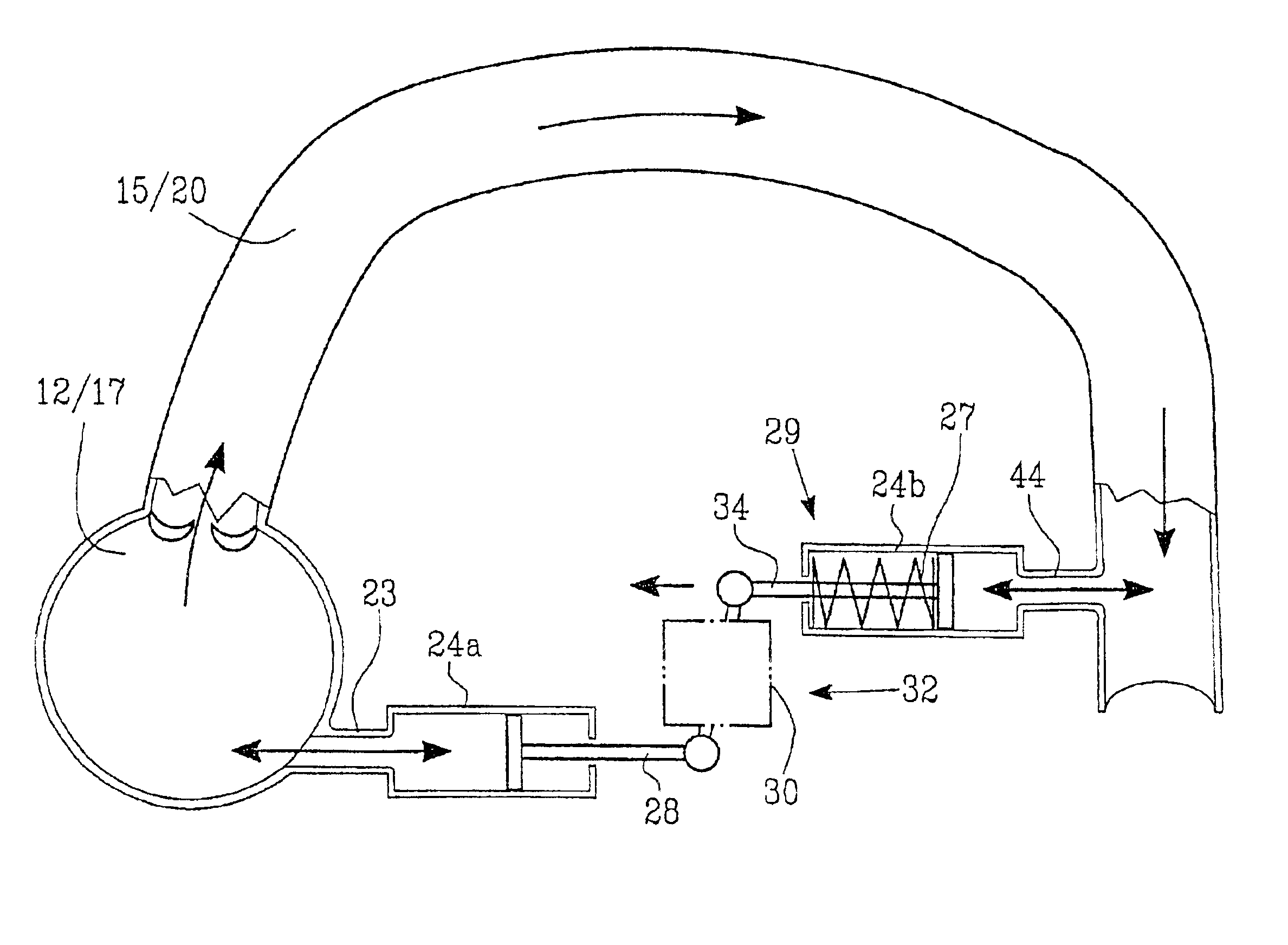
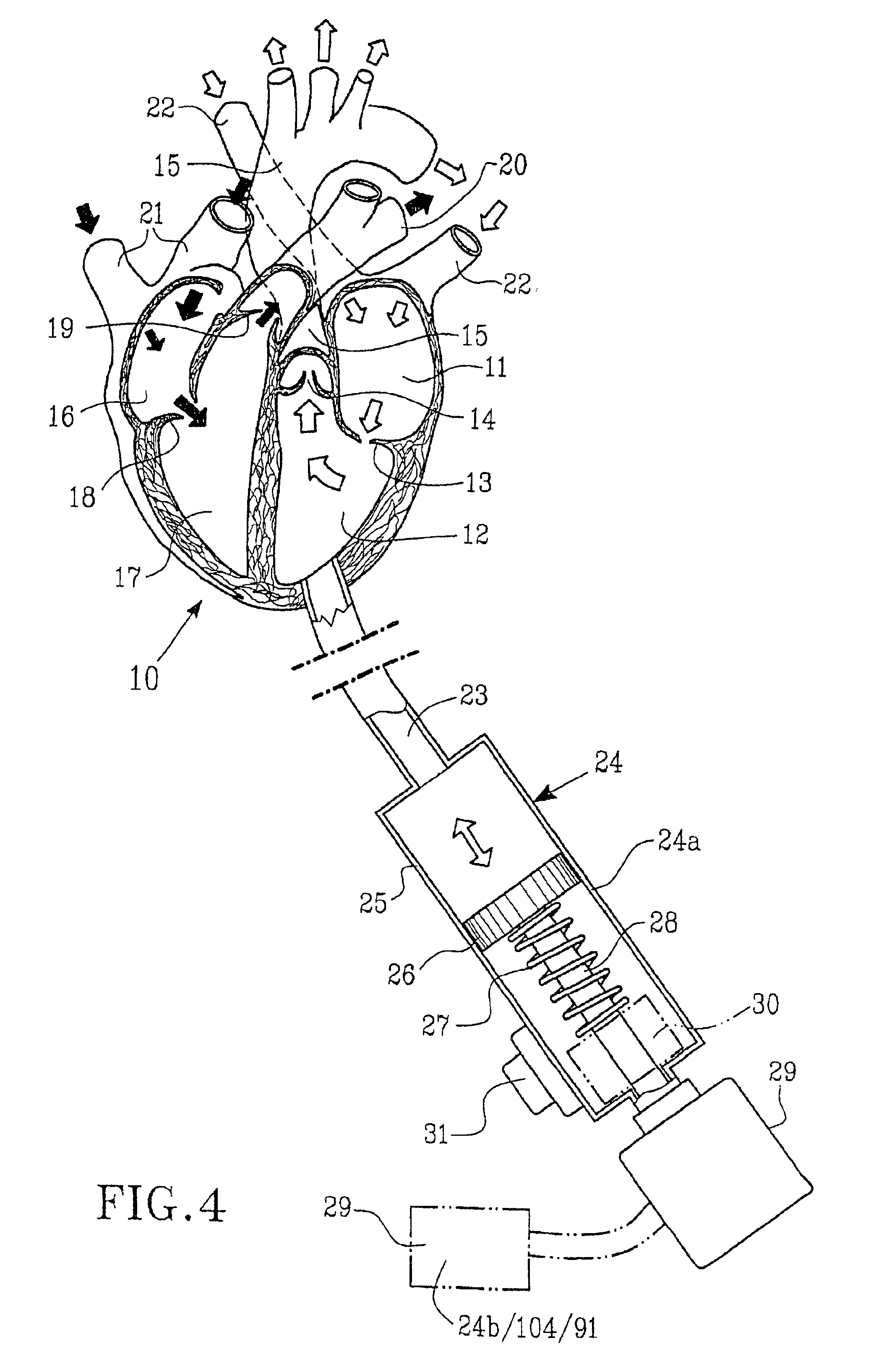
To get e better understanding of the invention, FIG. 4 demonstrates a human heart 10 partly in a 3 dimensional presentation, where 11 indicates the left atrium, 12 the left ventricle, 13 the mitral valve, 14 the aortic valve, 15 the main body artery (the aorta), 16 the right atrium, 17 the right ventricle, 18 the tricuspid valve, 19 the pulmonary valve, 20 the pulmonary artery, 21 two caval veins and 22 four pulmonary veins.

The blood is pumped from the circulatory system of the body (the periphery) via the two caval veins 21 to the right atrium 16, passes through the tricuspid valve 18 to the right ventricle 17 and is pumped through the pulmonary valve 19 to the pulmonary artery. In the lungs the blood absorbs oxygen and continues its flow to the pulmonary veins 22 to the left atrium 11 and further via the mitral valve 13 to the left ventricle 12, which pumps out the blood through the aortic valve 14 to the main body artery 15.

To the lower part of the left ventricle 12 is connected,...


PUM


Abstract

A device, potentially implantable in a living organism, intended to utilize at least a part of the hydraulic energy generated by the heart (10)-the primary unit-at the natural phases of work when the cavities of the heart (11, 12 and 16, 17) are filed with blood. The device includes at least one secondary unit (24), which is connectable to the cardiovascular system of the organism and arranged to utilize said hydraulic energy. The secondary unit is represented by at least one hydraulic motor (24a) arranged to transfer the hydraulic energy to a transferal organ (28). The transferal organ (28) is arranged to influence at least one tertiary unit, for example an executive device (29), which is constructed in order to convert the transferred energy to an alternative form of energy, with the purpose to influence certain defined functions within the organism. Preferably is arranged a regulating device (30) in order to control running parameters of the unit.

Description

The present invention refers to a device, implantable in a living organisms, for the utilisation of at least part of the hydraulic energy developed by the heart (the primary unit), which is acquired by the natural work of the heart i.e. by the contraction of the heart (the systolic phase) where the blood is put under pressure, followed by the relaxation phase (the diastole), where the ventricles of the heart are filled with blood. The device comprises at least one secondary unit connected to the cardiovascular system.THE BACKGROUND AND PROBLEMS OF THE INVENTIONThe heart is well known to work as two deplacement pumps which are functionally separated apart, and which work syncronously, in the way that the right pump transports blood to the the pulmonary circulation, whereafter the oxygenated blood returns to the left pump. Thereafter, the left side ejects the oxygenated blood to the peripheral circulation of the body i.e to the vascular system of the entire organism. Finally, the bloo...

Claims


Application Information

Patent Timeline
Patent Type & Authority Patents(United States)
IPC IPC(8): A61M27/00A61M1/12A61M1/10A61N1/08A61F2/24A61M1/16
CPCA61M1/127A61M27/002A61N1/08A61M1/107A61M1/1081A61N1/3785A61M1/16A61M60/882A61M60/562A61M60/857A61M60/113A61M60/274A61M60/258A61M60/871A61M60/427A61M60/538A61M60/178A61M60/515
Inventor BUGGE, MOGENSPALMERS, GORAN
Owner BUGGE MOGENS
Why Eureka
Try Eureka