Upper arch effect demonstrating instrument

A technology of soil arch effect and demonstrator, which is applied in the field of experimental devices to achieve the effect of image interaction

Inactive Publication Date: 2007-06-06
ZHEJIANG UNIV
View PDF0 Cites 7 Cited by
  • Summary
  • Abstract
  • Description
  • Claims
  • Application Information

AI Technical Summary

Problems solved by technology

However, in practice there are situations in which a soil mass can remain stable without some or all of it being supported, such as animal burrows

Method used


Image

  • Upper arch effect demonstrating instrument

Examples


Embodiment Construction

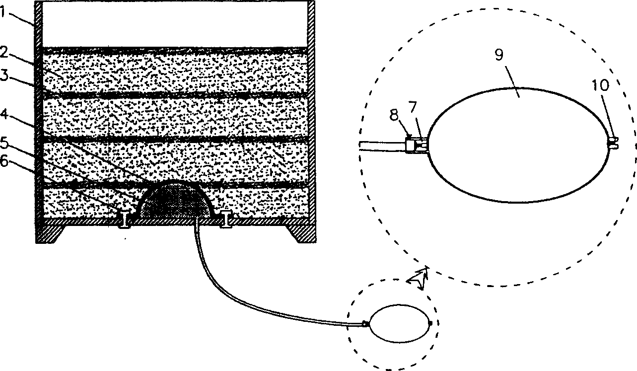
[0008] As shown in the drawings, the present invention includes a plexiglass box 1, yellow sandy soil 2, black sandy soil 3, elastic rubber film 4, semi-cylindrical rubber air bag 5, fixing bolt 6, front one-way valve 7, air release valve 8, air bag 9, rear one-way valve 10. A semi-cylindrical rubber air bag 5 is installed at the center of the bottom of the plexiglass case 1, and an elastic rubber film 4 is installed on the outside of the semi-cylindrical rubber air bag 5, both of which are fixed on the bottom of the plexiglass case 1 with bolts 6; organic Yellow sandy soil 2 and black sandy soil 3 are filled successively in the glass box 1 from bottom to top; the semi-cylindrical rubber air bag 5 is connected to the air bag 9 outside the plexiglass box 1 with a pipe; Air valve 8 and front one-way valve 7, also be connected with rear one-way valve 10 on the air bag 9.

[0009] The present invention is made up of square plexiglass box 1 and inflatable semicylindrical rubber ai...


PUM


Abstract

The invention discloses a soil arching effect demonstrator. There is a half cylindrical rubber airbag in the center of the bottom of Perspex box. Outside the airbag there is flexible rubber membrane. They are fixed at the bottom of Perspex box. From bottom to top, the Perspex box is filled with yellow sand and black sand; tube of the airbag is connected with inflatable bag outside the Perspex box; in the tube of inflatable bag, there is release valve and forward one-way valve; there is one backward one-way valve in the inflatable bag. By giving air and releasing air, the soil arching can be directly observed.

Description

technical field [0001] The invention relates to an experimental device, in particular to a soil arch effect demonstrator. Background technique [0002] Soil (such as sand) is a kind of granular material. Theoretically speaking, this kind of granular material needs certain support to be stable, such as the lining of underground tunnels and the support of foundation pits. However, in practice there are situations in which parts or all of the soil can remain stable without support, such as animal burrows. This is due to the soil arching effect. Due to the soil arching effect, the vertical earth pressure acting on the tunnel lining is often less than the self-weight stress of the overlying soil layer. The soil arching effect also affects the measurement of earth pressure in the field soil. The mechanism of the soil arch effect: In practice, there are often differences in the degree of support of various parts of the soil, and there is a relative sliding tendency between soil...

Claims


Application Information

Patent Timeline
Patent Type & Authority Applications(China)
IPC IPC(8): G09B23/40G09B25/00
Inventor 詹良通王顺玉陈云敏
Owner ZHEJIANG UNIV
Why Eureka
Try Eureka