Dynamic vibration absorber and optical disk device

A technology of optical disc device and shock absorber, applied in the direction of poor vibration/sound insulation/absorption, head configuration/installation, planar record carrier equipment, etc., can solve problems such as limitations and inability to use dynamic shock absorbers, and achieve the elimination of design restrictions Effect

Inactive Publication Date: 2011-05-11
YAMAUCHI CORP
View PDF5 Cites 0 Cited by
  • Summary
  • Abstract
  • Description
  • Claims
  • Application Information

AI Technical Summary

Problems solved by technology

like Figure 5 As shown, since the dynamic shock-absorbing member 55 is mounted on or under the base frame 52 through the elastic bodies 54a, 54b, in order to ensure a structural gap with the optical disk and a gap with the housing, it is limited by the design of the components.
In addition, dynamic shock absorbers have not been able to be used in thin models and thin drivers for notebook computers so far because they must have a specified thickness.

Method used


Image

  • Dynamic vibration absorber and optical disk device
  • Dynamic vibration absorber and optical disk device
  • Dynamic vibration absorber and optical disk device

Examples


Embodiment Construction

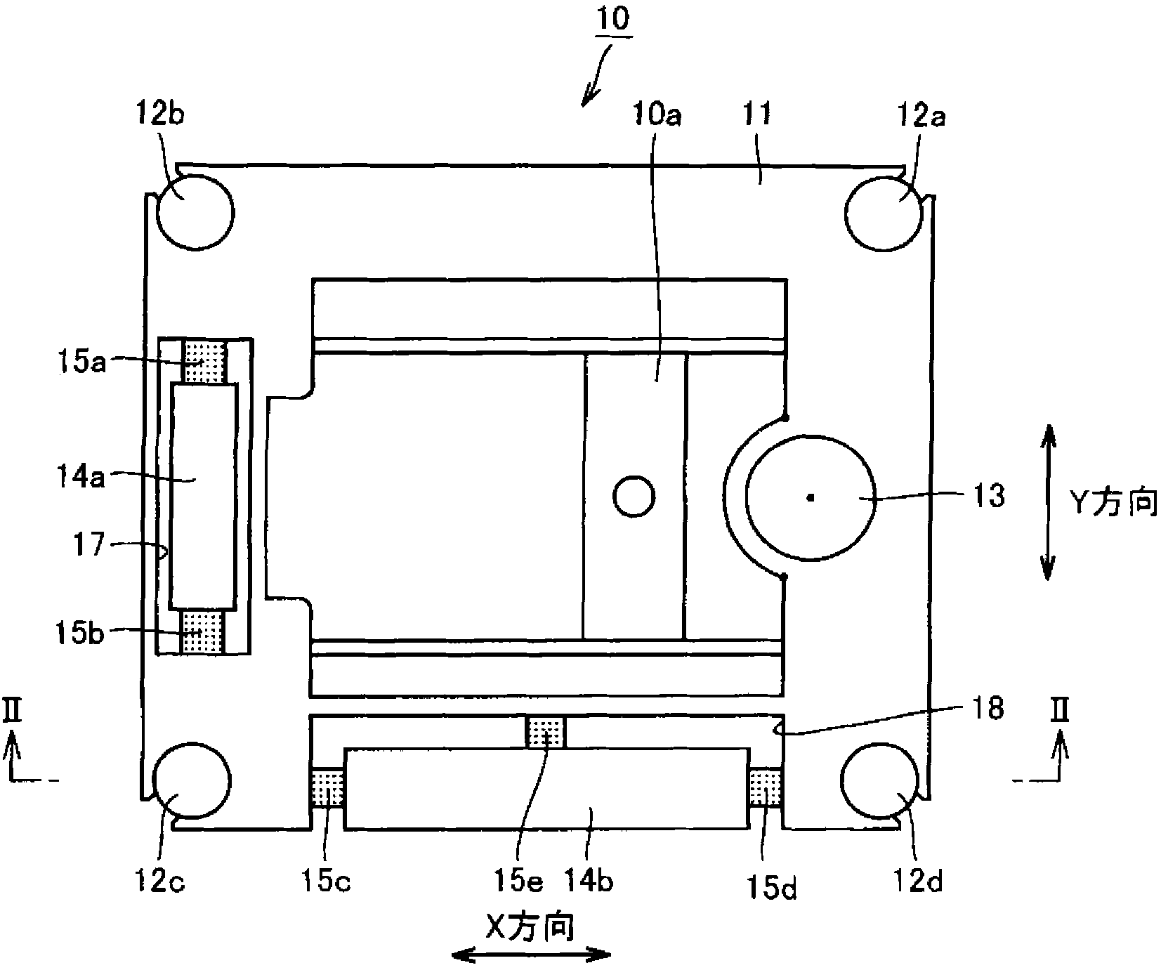
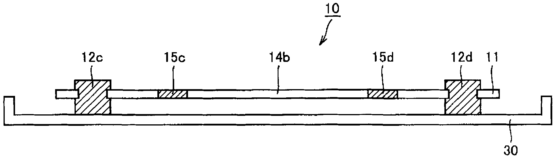
[0025] Embodiments of the present invention will be described below with reference to the drawings. figure 1 It is a plan view showing a dynamic shock absorber according to an embodiment of the present invention and an optical disc device using the dynamic shock absorber, figure 2 yes figure 1 Sectional view of the part shown in II-II. In addition, in figure 2 In , no hatching is drawn for dynamic shock absorbers. Also, in this embodiment, the dynamic shock absorber based on the present invention is applied to a half-height optical disc device. In addition, the optical disc device here refers to a device that drives an optical drive such as CD, CD-ROM, DVD, DVD-ROM, or an optical disc such as a magneto-optical disc or a large-capacity floppy disc.

[0026] refer to figure 1 as well as figure 2 The optical disk device 10 includes a rectangular planar base frame 11 and second elastic bodies 12a to 12d provided at the four corners of the base frame 11, and the base fr...


PUM


Abstract

A dynamic vibration absorber comprises a base chassis (11) holding a spindle motor (13) rotatingly driving a mass-eccentric disk (unshown), a dynamic vibration absorbing element (14a) connected to the base chassis (11) through first elastic bodies (15a) and (15b), and a dynamic vibration absorbing element (14b) connected to the base chassis (11) through first elastic bodies (15c) to (15e). The base chassis (11) and the dynamic vibration absorbing elements (14a) and (14b) are installed on an approximately same plane.

Description

technical field [0001] The invention relates to a dynamic shock absorber and an optical disc device using the dynamic shock absorber, in particular to a flat dynamic shock absorber and an optical disc device using the dynamic shock absorber. Background technique [0002] For example, JP-A-2001-256762 and JP-A-2001-355670 disclose conventional dynamic shock absorbers for optical discs. Figure 5 It is a schematic diagram showing simplified configurations of main parts of the optical disc devices disclosed in JP-A-2001-256762 and JP-A-2001-355670. [0003] refer to Figure 5 In a conventional optical disc device, a spindle motor for rotationally driving the optical disc, a head for reading information on the optical disc, and the like are attached to the chassis 52, and the chassis 52 is attached to the housing 51 via elastic bodies 53a, 53b. [0004] In recent years, the rotational speed of optical discs has increased, and a dynamic shock absorber has been installed in order ...

Claims


Application Information

Patent Timeline
Patent Type & Authority Patents(China)
IPC IPC(8): G11B33/08
CPCA61P31/04G11B33/08G11B7/08G11B25/04
Inventor 齐藤利夫
Owner YAMAUCHI CORP
Why Eureka
Try Eureka