Drainage pipe structure of window-type air-conditioner

A technology for drainage pipes and air conditioners, which is applied in air conditioning systems, heating methods, and prevention of condensate water, can solve problems such as difficult installation, affect drainage, and damage to drainage pipes, and achieve the effects of easy insertion and removal, convenient installation, and not easy damage.

Inactive Publication Date: 2007-06-13
LG ELECTRONICS (TIANJIN) APPLIANCES CO LTD
View PDF0 Cites 7 Cited by
  • Summary
  • Abstract
  • Description
  • Claims
  • Application Information

AI Technical Summary

Problems solved by technology

[0005] The above-mentioned installation structure of the drain pipe is not easy to install because the pipe head of the drain pipe is slightly larger than the dra

Method used


Image

  • Drainage pipe structure of window-type air-conditioner
  • Drainage pipe structure of window-type air-conditioner

Examples


Example Embodiment

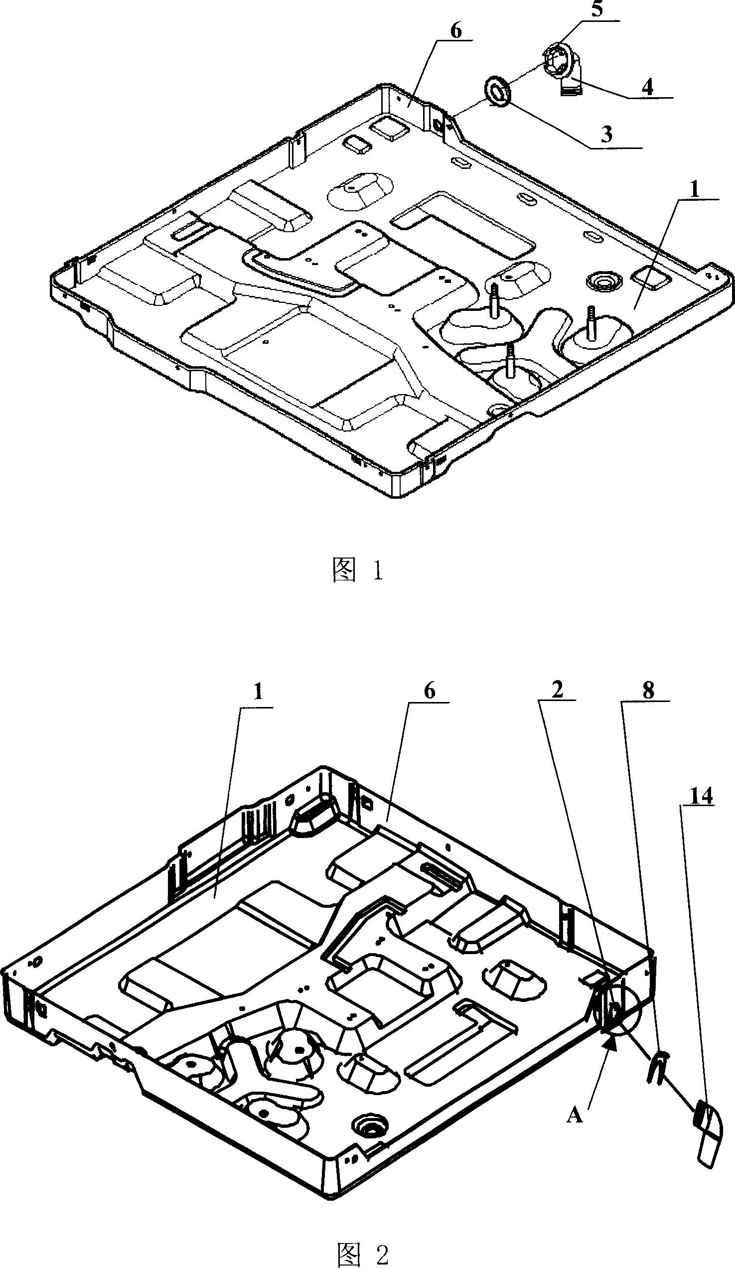
[0022] Hereinafter, the drainage pipe structure of the window air conditioner of the present invention will be described in detail with reference to the drawings and specific embodiments.

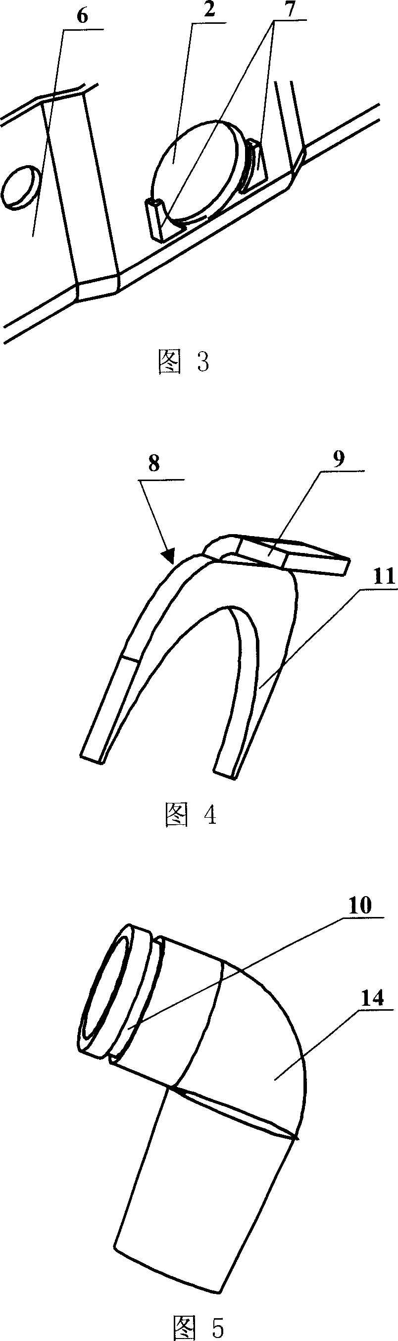
[0023] The drainage pipe structure of the window type air conditioner of the present invention includes a chassis 1 with drainage holes 2 on its side 6, and also includes a plug-in card 8 and a drainage that can be inserted into the drainage hole 2 and communicate with the drainage hole 2. The drain pipe 14 is in the shape of an elbow. A slot 10 for inserting the card 8 is formed on one end of the drain hole 2 of the drain pipe 14, corresponding to the positions on both sides of the drain hole 2 and at the bottom of the chassis 1 A slot 7 into which a card 8 can be inserted is provided.

[0024] The plug-in card 8 includes an integrally formed plug handle 9 located at the upper end, and an inverted U-shaped pin 11 located on the lower side of the plug handle 9 for inserting into a pair of slots...


PUM


Abstract

The invention relates to a drain pipe structure of wall-through type air conditioner that includes bottom with drainage-hole, drain pipe, blocking groove and inserting groove. The inserting card includes an inserting handle, and U shaped inserting feet. The invention fixes drain pipe onto drainage-hole through inserting card with inserting feet. It is easy to inserting and drawing. The installation of drain pipe is convenient. The useful life and installation efficiency of drain pipe are improved.

Description

technical field [0001] The invention relates to a window type air conditioner. In particular, it relates to a drainpipe structure of a window type air conditioner which is easy to install and not easily deformed when inserted or pulled out. Background technique [0002] Generally, air conditioners are generally classified into split type air conditioners and integrated type air conditioners. Split type and integrated type air conditioners have the same function. That is, an indoor device with cooling is installed on the indoor side, an outdoor device with heat dissipation and compression is installed on the outdoor side, and the outdoor and indoor devices are connected by refrigerant pipes. The device installed on the outdoor side includes a condenser (outdoor heat exchanger) and a compressor, and the device installed on the indoor side includes an evaporator (indoor heat exchanger). Both the evaporator installed on the indoor side and the condenser and compressor install...

Claims


Application Information

Patent Timeline
IPC IPC(8): F24F13/22F24F1/02
Inventor 刘震
Owner LG ELECTRONICS (TIANJIN) APPLIANCES CO LTD
Why Eureka
Try Eureka