
Intervertebral implant

a technology of intervertebral discs and implants, which is applied in the field of intervertebral discs, can solve the problems of wear on the joint surfaces, inability to achieve mobility that is identical to the natural mobility of the intervertebral disks,

Inactive Publication Date: 2005-04-14
AESCULAP AG
View PDF99 Cites 19 Cited by
  • Summary
  • Abstract
  • Description
  • Claims
  • Application Information

AI Technical Summary

Benefits of technology

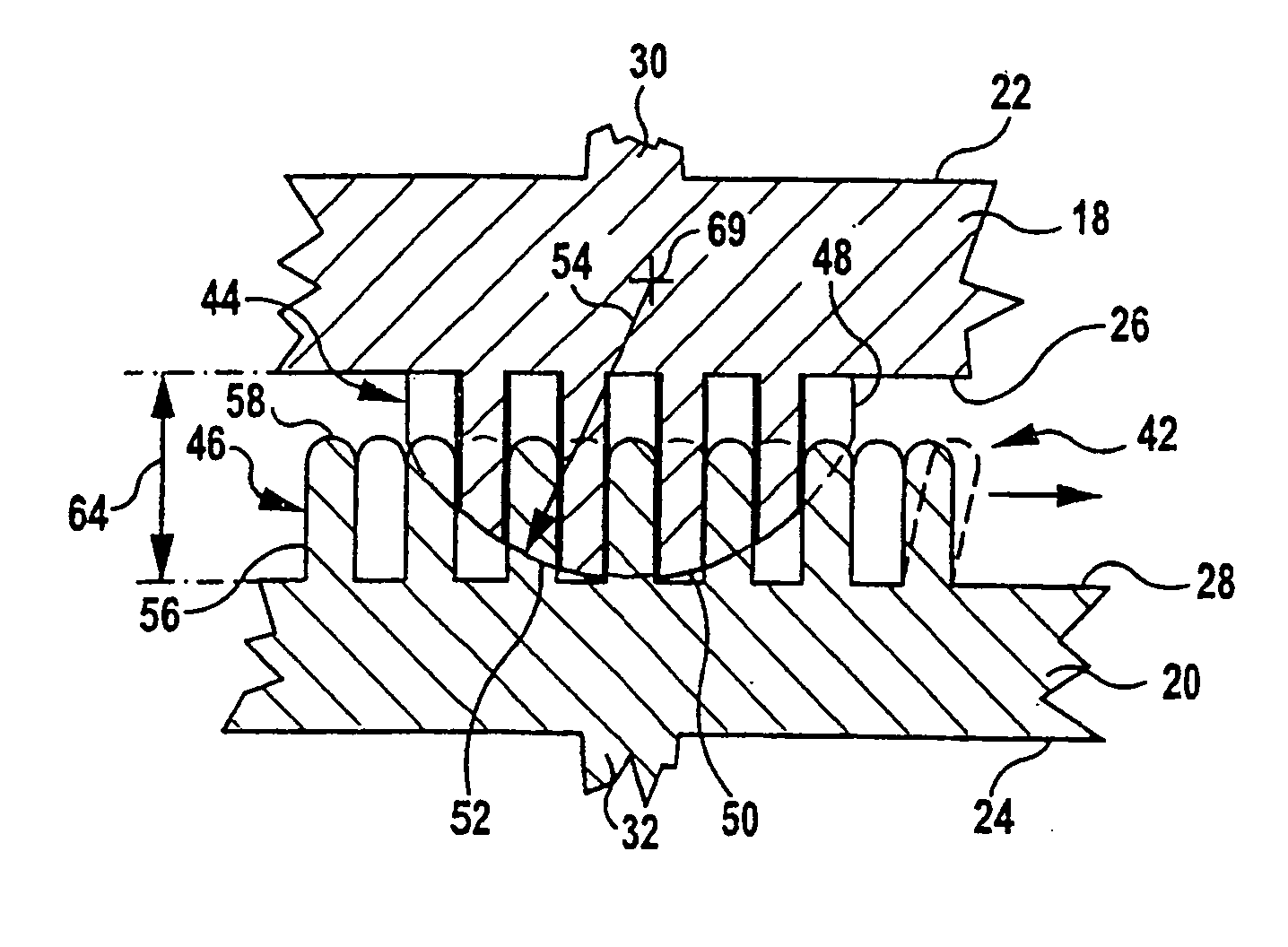
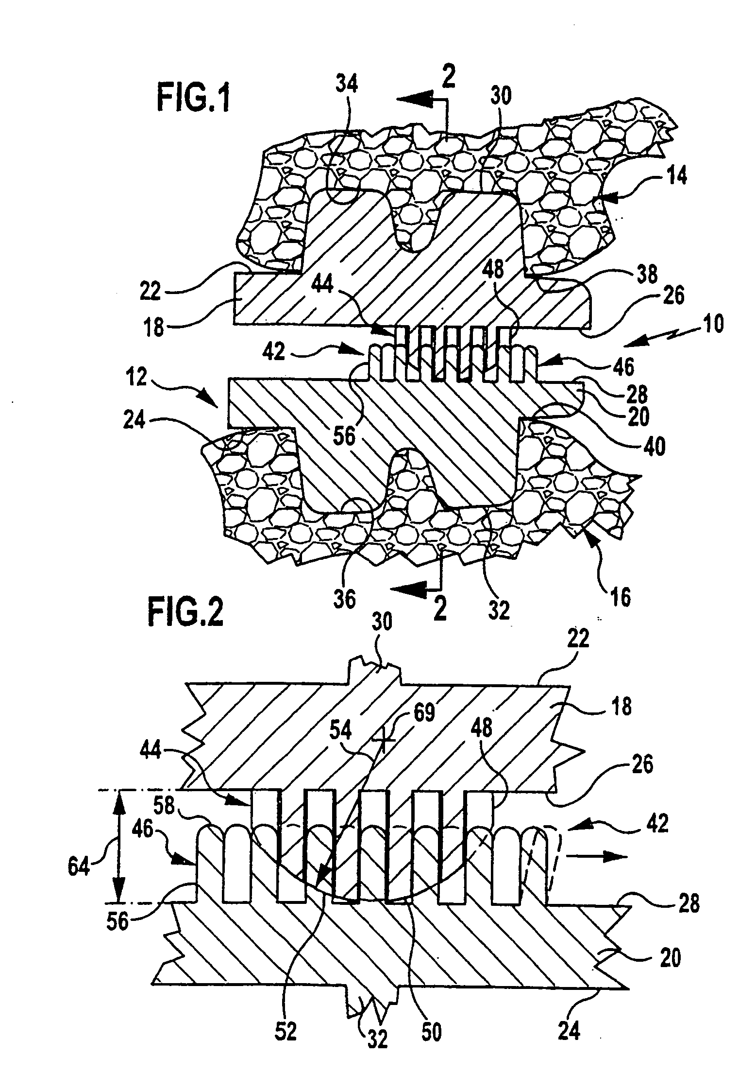
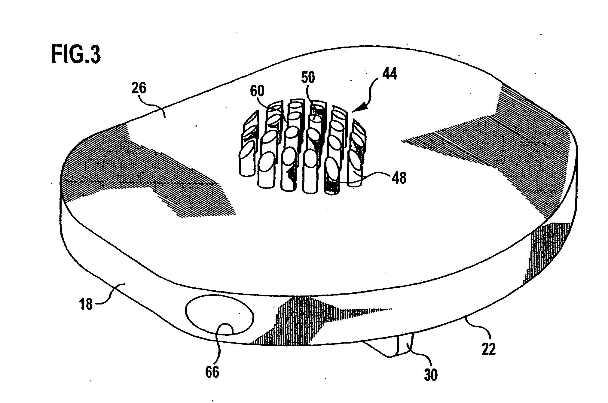
[0008] The present invention pertains to an intervertebral implant for insertion between first and second vertebral bodies defining an intervertebral space, with a first anchoring part for anchoring at the first vertebral body, with a second anchoring part for anchoring at the second vertebral body and with a joint, which connects the first and second anchoring parts and which comprises a first joint part and a second joint part, wherein the first anchoring part carries the first joint part and the second anchoring part carries the second joint part. The first joint part comprises a plurality of joint elements projecting in the direction of the second anchoring part, the second joint part comprises a plurality of joint elements projecting in the direction of the first anchoring part, and the joint elements of both joint parts are arranged and designed such that after the insertion of the intervertebral implant into the intervertebral space, they mesh with intermediate spaces between joint elements of the other joint part and make possible the tilting of the two anchoring parts in relation to one another.
[0009] Due to this design, the two joint parts can be plugged easily into one another. Moreover, especially good hold of the two joint parts in relation to one another is achieved due to the joint elements meshing with one another. Furthermore, an intervertebral implant designed in this manner makes it possible that a joint center defined by the two joint parts, for example, a rotation center, is not located in a defined position in relation to the two anchoring parts. Instead, such an intervertebral implant can migrate in the intervertebral space, exactly as it happens in the natural intervertebral disk. A translational motion within the intervertebral space of a joint center is possible depending on the design of the joint elements and the size of the intermediate spaces. Moreover, the number of support points is determined by the number of the projecting joint elements, which in turn leads to a reduction of the wear of the implant.
[0010] It is favorable if the joint elements comprise projections projecting perpendicularly or substantially perpendicularly from the anchoring parts. Such joint elements can have an especially simple design. Furthermore, their properties can be set very easily in the desired manner, for example, by selecting a special shape or by selecting certain materials.

Problems solved by technology

However, a mobility that is identical to the natural mobility is not yet reached in any of the prior-art intervertebral disk prostheses.
Another problem in prior-art intervertebral disk prostheses is the wear on the joint surfaces, which happens regardless of whether these are made of plastic or metal.

Method used


Image

  • Intervertebral implant
  • Intervertebral implant
  • Intervertebral implant

Examples


Embodiment Construction

[0046] Although the invention is illustrated and described herein with reference to specific embodiments, the invention is not intended to be limited to the details shown. Rather, various modifications may be made in the details within the scope and range of equivalents of the claims and without departing from the invention.

[0047]FIG. 1 shows an intervertebral disk prosthesis designated as a whole by the reference number 10. It is inserted into an intervertebral space 12 between a first vertebral body 14 and a second vertebral body 16.

[0048] The intervertebral disk prosthesis 10 has a two-part design and comprises a first carrier plate 18 and a second carrier plate 20, which comprise a respective anchoring surface 22 and 24 and a respective bearing surface 26 and 28. Narrow, plate-like anchoring ribs 30 and 32, which are driven into the vertebral bodies 14 and 16, respectively, to anchor the carrier plates 18 and 20 or are inserted into recesses 34 and 36 prepared therein for this...


PUM


Abstract

An intervertebral implant is provided for insertion between first and second vertebral bodies defining an intervertebral space. The intervertebral implant includes a first anchoring part for anchoring the intervertebral implant at the first vertebral body, a second anchoring part for anchoring the intervertebral implant at the second vertebral body, and a joint connecting the first and second anchoring parts. Joint elements of a first joint part are configured to mesh with respective ones of intermediate spaces of a second joint part and joint elements of the second joint part are configured to mesh with respective ones of intermediate spaces of the first joint part upon insertion of the intervertebral implant into the intervertebral space, thereby facilitating the tilting of the first and second anchoring parts in relation to one another.

Description

[0001] This application is related to and claims the benefit of German Utility Model No. 203 15 613.7 entitled Intervertebral Implant issued on Dec. 12, 2003, and German Patent Application No. 103 47 175.8 filed Oct. 8, 2003. FIELD OF THE INVENTION [0002] The present invention pertains to an intervertebral implant, with which the original height of the intervertebral disk can be restored, e.g., in degeneratively altered intervertebral disks, and the function is preserved at the same time. BACKGROUND OF THE INVENTION [0003] Intervertebral implants are used as artificial intervertebral disk prostheses in intervertebral spaces of the human spinal column and are known in numerous embodiment variants. Numerous artificial intervertebral disk prostheses are based on the ball and socket joint principle. [0004] For example, an intervertebral disk prosthesis with a ball and socket joint, which has a rotation center that can be fixed in relation to the anchoring parts, is known from WO 01 / 0189...

Claims


Application Information

Patent Timeline
IPC IPC(8): A61F2/00A61F2/30A61F2/44A61F2/46
CPCA61F2/4425A61F2/4611A61F2002/30331A61F2002/30405A61F2002/30448A61F2002/30563A61F2310/00029A61F2002/30884A61F2220/0025A61F2220/0033A61F2220/005A61F2310/00023A61F2002/30808
Inventor SCHULTZ, ROBERTALTERMANN, FRANK
Owner AESCULAP AG
Learn More