Screen printing device

A technology of screen printing and carrying device, which is applied in the direction of screen printing machine, printing machine, printing machine, etc., can solve the problem of difficult circuit substrate clamping and so on.

Active Publication Date: 2010-09-29
YAMAHA MOTOR CO LTD
View PDF3 Cites 2 Cited by
  • Summary
  • Abstract
  • Description
  • Claims
  • Application Information

AI Technical Summary

Problems solved by technology

Therefore, even if one of the pair of jigs holding the side of the circuit board collides with the side of the circuit board and moves to the other jig to hold the circuit board, since the circuit board is fixed, Therefore, it is difficult to reliably clamp the circuit board in a state where the warped state is corrected.

Method used


Image

  • Screen printing device
  • Screen printing device
  • Screen printing device

Examples


Embodiment Construction

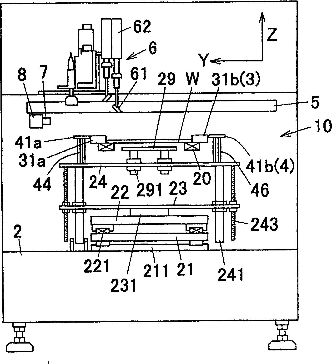
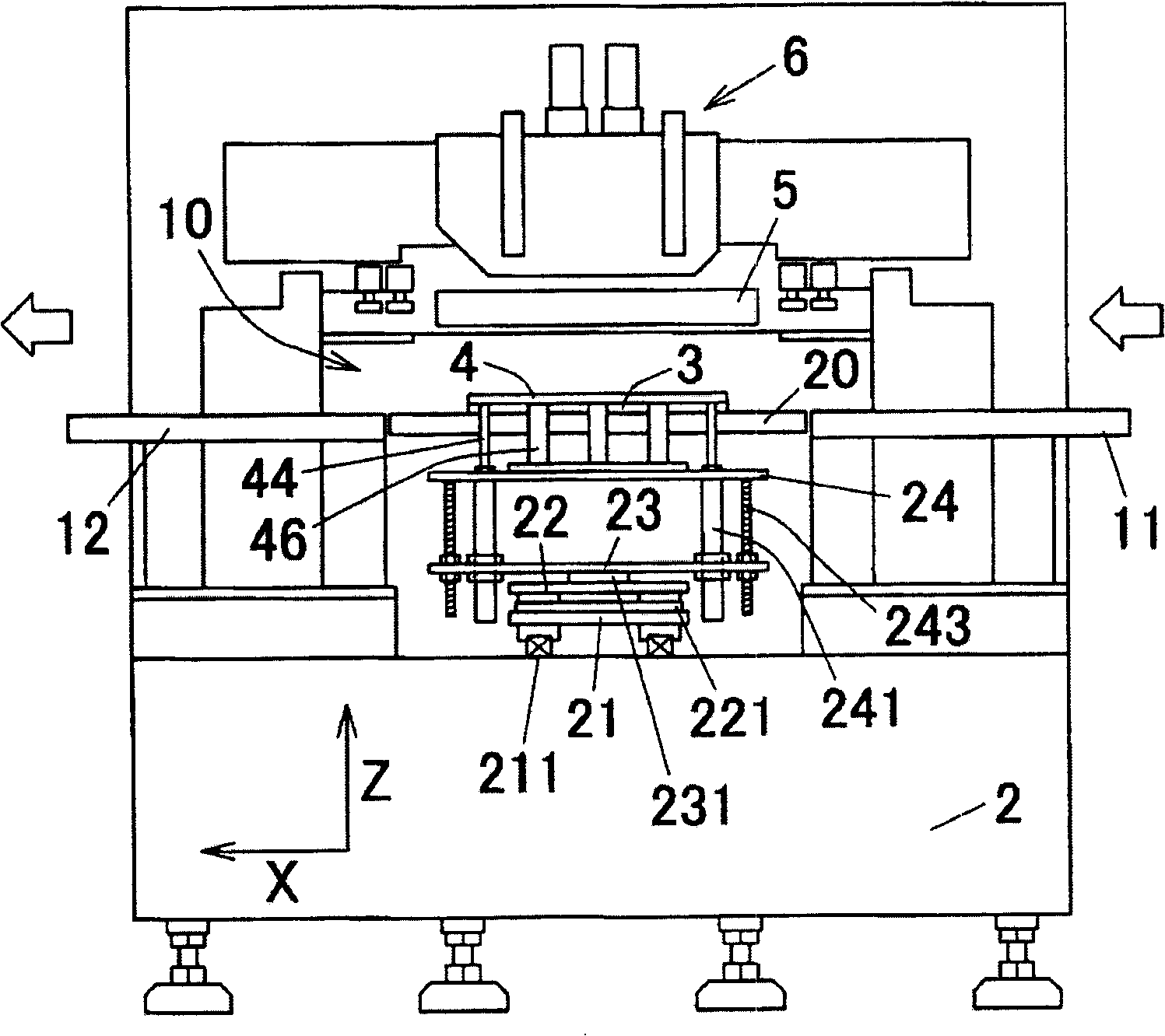
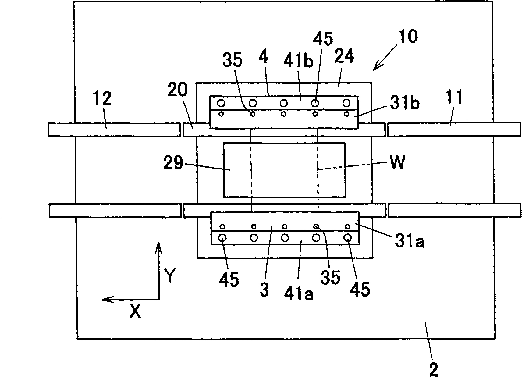
[0029] figure 1 It is a side view of a screen printing device according to an embodiment of the present invention, figure 2 is the front view of the device, image 3 is the top view of the device, Figure 4 It is a perspective view of the printing table 10 of the apparatus and its surroundings. As shown in the above figure, on the base 2 of the screen printing device (referred to as the printing device), a printing table 10 is provided, and on both sides of the printing table 10, along the X-axis direction (transport line) are provided with The substrate W is carried into the upstream conveyor belt 11 of the printing table 10 and carried out from the downstream conveyor belt 12 of the printing table 10 .

[0030] Moreover, the printing device also includes a clamp assembly 3 for clamping the circuit substrate W; a positioning assembly 4 for abutting against the upper surface of the circuit substrate W when clamping the circuit substrate W to position it; a mask assembly 5 ...


PUM


Abstract

A screen printing apparatus of the invention comprises: a supporting device supporting a circuit substrate from below; a clamp, from both sides, holding the side surface of the circuit substrate supported by the supporting device; a circuit substrate pressing device for pressing the circuit substrate from above, which is supported on the supporting device and maintaining the circuit substrate in a warp and then straightened state along an up-and-down direction. The circuit substrate pressing device holds the circuit substrate to move the same along a holding direction of the clamp. According to the invention, via the circuit substrate pressing device pressing the circuit substrate, a warp of the circuit substrate can be straightened and the circuit substrate can be maintained in this state.

Description

technical field [0001] The present invention relates to a screen printing device for coating a paste such as cream solder on a circuit board. Background technique [0002] In conventional screen printing devices, the squeegee moves (rotates) on the mask with the circuit board and the mask set on the printing table generally overlapped, and the creamy solder supplied to the mask, conductive Paste such as paste is printed (applied) on a predetermined position on the circuit board through openings (mask openings) formed in the mask. [0003] The printing table of the above screen printing device includes, from below, a carrier device that supports the circuit board that is carried in substantially horizontally by a conveyor belt; A pair of clamps that overlap the matte. As a result, the above-mentioned circuit board is warped in the vertical direction as a whole, and if the circuit board in the warped state is clamped by the above-mentioned jig, an unnecessary gap will be gen...

Claims


Application Information

Patent Timeline
Patent Type & Authority Patents(China)
IPC IPC(8): B41F15/08B41F15/26H05K3/34H05K3/12
Inventor 墨冈浩一
Owner YAMAHA MOTOR CO LTD
Why Eureka
Try Eureka