Mold unit

A technology of mold and embedded block, applied in the field of plastic injection mold device, can solve problems such as difficulty in height and depth, difficulty in ensuring mold clamping accuracy, etc., and achieve the effect of simplifying cumbersome structure

Inactive Publication Date: 2007-06-27
HONG FU JIN PRECISION IND (SHENZHEN) CO LTD +1
View PDF0 Cites 5 Cited by
  • Summary
  • Abstract
  • Description
  • Claims
  • Application Information

AI Technical Summary

Problems solved by technology

However, in the actual manufacturing process, it is very difficult to make the first embedded block 12 and the second embedded block 13 have the required precise height and depth, so it is difficult to ensure the accuracy of mold clamping

Method used


Image

  • Mold unit
  • Mold unit
  • Mold unit

Examples


no. 1 example

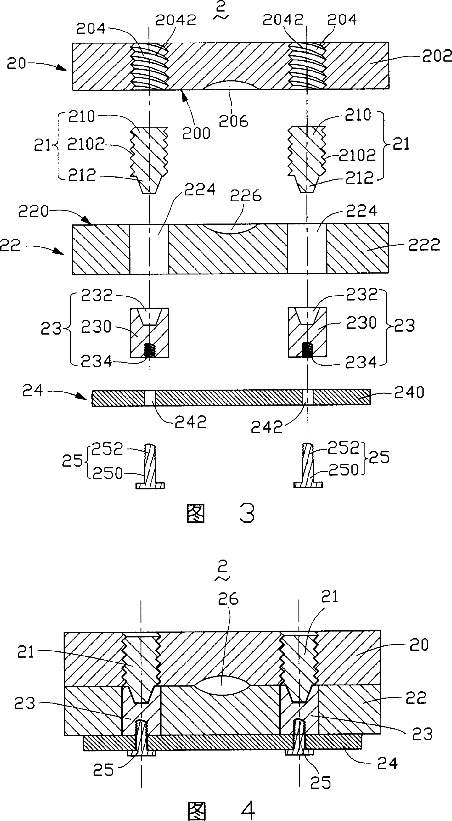
[0017] Referring to FIG. 3 and FIG. 4 , a mold device 2 provided by the first embodiment of the present invention includes an upper module 20 , a first embedded block 21 , a lower module 22 , a second embedded block 23 , a backing plate 24 and bolts 25 .

[0018] The upper module 20 includes a base body 202 , the base body 202 has a first surface and an opposite second surface, and the second surface is the parting surface 200 . The base body 202 also defines a first through hole 204 penetrating through the base body 202 , and the first through hole 204 extends from the first surface to the second surface (ie, the parting surface 200 ). The shape of the first through hole 204 may be cylindrical, and an internal thread 2042 is formed on the inner wall surface constituting the through hole. The upper module 20 also includes an upper mold cavity 206 formed at an end of the upper module 20 close to the parting surface 200 and extending from the parting surface 200 .

[0019] Each...

no. 2 example

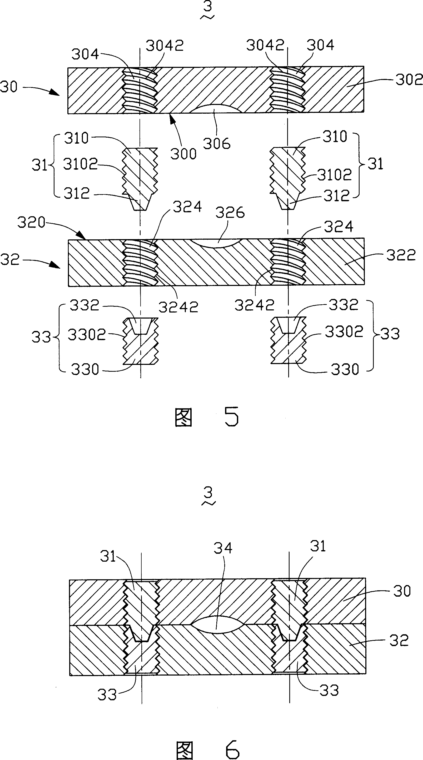
[0028]Referring to FIG. 5 and FIG. 6 , a mold device 3 provided by the second embodiment of the present invention includes an upper module 30 , a first insert block 31 , a lower module 32 , and a second insert block 33 .

[0029] The upper module 30 includes a base body 302 , the base body 302 has a first surface and an opposite second surface, and the second surface is the parting surface 300 . The base body 302 also defines a first through hole 304 penetrating through the base body 302 , and the first through hole 304 extends from the first surface to the second surface (ie, the parting surface 300 ). The shape of the first through hole 304 may be cylindrical, and an internal thread 3042 is formed on the inner wall surface constituting the through hole. The upper module 30 also includes an upper mold cavity 306 formed at an end of the upper module 30 close to the parting surface 300 and extending from the parting surface 300 .

[0030] The first embedded block 31 includes a...


PUM


Abstract

The mold unit includes one upper mold with one first through hole, one lower mold with one second through hole, and one locating set with one first embedded block and one second embedded block for being held into the first through hole and second through hole separately. The first embedded block has one locating pin in one end and the second embedded block has one locating hole in one end opposite to and fitting to the locating pin. The first embedded block has outer thread and the first through hole has inner thread to match the outer thread for the locating pin and the locating hole to match tightly.

Description

【Technical field】 [0001] The invention relates to a plastic injection mold device, in particular to a mold device which realizes precise positioning by adjusting the expansion and contraction of positioning pins. 【Background technique】 [0002] At present, in products such as electronics, automobiles, motors, electrical appliances, instruments and meters, home appliances and communications, 70% to 90% of parts are manufactured by mold forming, and molds have become an important equipment for industrial production. Moreover, most of the plastic products are made by injection molding devices. [0003] The mold device disclosed in the prior art includes an upper module and a lower module, and when using this kind of mold for molding, especially during the mold closing process, the precise positioning of the upper module and the lower module is very important. Usually, when the mold is closed, the positioning pin and the positioning hole matching the positioning pin are used fo...

Claims


Application Information

Patent Timeline
Patent Type & Authority Applications(China)
IPC IPC(8): B29C33/30B29C45/26
Inventor 杜健生
Owner HONG FU JIN PRECISION IND (SHENZHEN) CO LTD
Why Eureka
Try Eureka