Improved intraoperation stent system

A stent system and covered stent technology, applied in the field of medical devices, can solve the problems that the stent system cannot be used well, cannot be used for hybrid surgery, is easy to inhale or become infected, etc., so as to eliminate the risk of scratching blood vessels, Small size and easy positioning effect

Active Publication Date: 2011-11-23
SHANGHAI MICROPORT ENDOVASCULAR MEDTECH (GRP) CO LTD
View PDF6 Cites 26 Cited by
  • Summary
  • Abstract
  • Description
  • Claims
  • Application Information

AI Technical Summary

Problems solved by technology

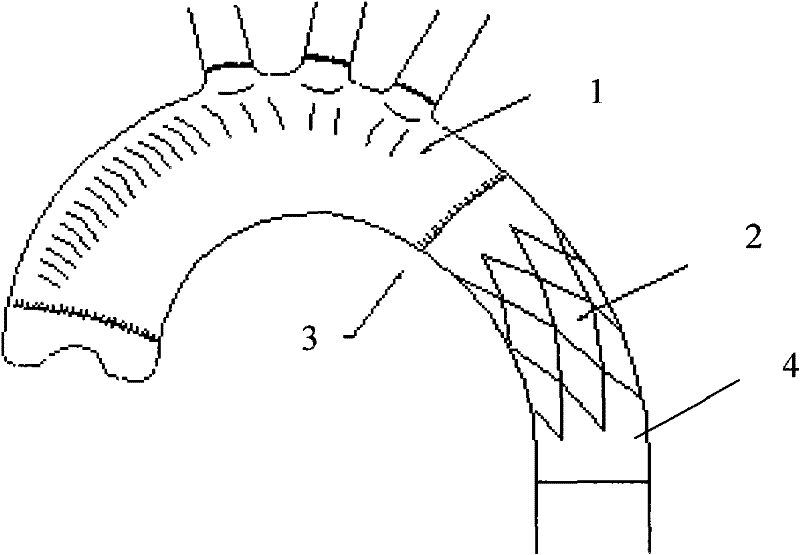
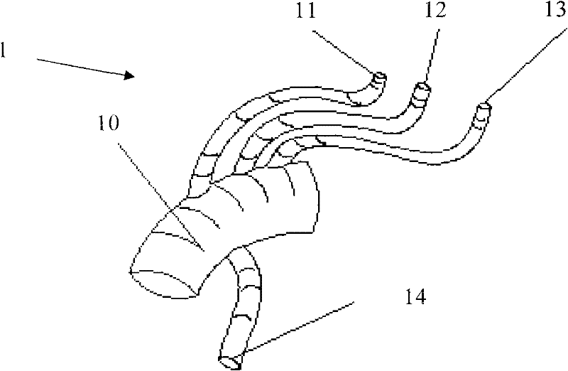
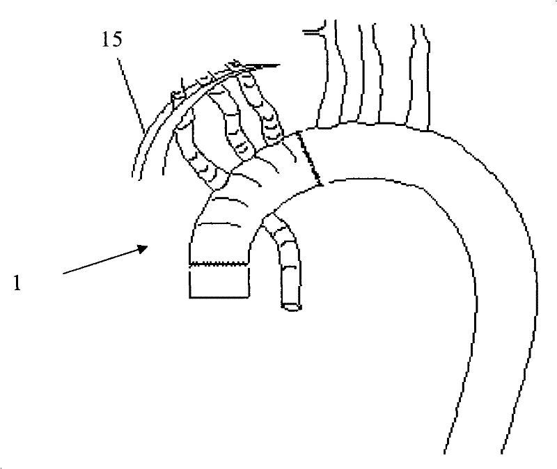
[0012] 1. The operation process requires deep hypothermic circulatory arrest (DHCA), which has high requirements for patients before operation and difficult recovery after operation
[0013] 2. The cooling and heating of the deep hypothermic cycle arrest require a long operating time, which is a test for the physical strength of the patient and the doctor
[0014] 3. The blood vessels are open during the operation, and it is easy to get air or be infected. During the operation, exhaust gas is required and the requirements are high
[0028] 4. The stent graft and its delivery system must have the function of retrograde introduction and release
[0031] However, the stents of the above two patents and their delivery systems have no reduced profile design, and the flexibility is not enough, and no markings are provided on the delivery system
In addition, the CN200420095867.1 patent also needs to make a large incision on the aorta to allow the intraoperative stent delivery system to pass through, while the CN200420103630.3 patent has the function of retrograde release, but it cannot be used for the above-mentioned hybrid surgery
Therefore, the stent systems of the above two patents cannot be well used in the above-mentioned hybrid surgery

Method used


Image

  • Improved intraoperation stent system
  • Improved intraoperation stent system
  • Improved intraoperation stent system

Examples


Embodiment Construction

[0061] Embodiments of the present invention will be described in detail below with reference to FIGS. 7-12.

[0062] Referring to FIG. 7, the intraoperative stent system 100 of the present invention includes an outer tube 110, an inner tube 111 sleeved in the outer tube 110 and movable relative to the outer tube 110, and a control guide wire located inside the outer tube 110 that can be introduced and withdrawn. 125 and the stent graft placed between the outer tube 110 and the inner tube 111 (see Figure 8 ), wherein the inner tube 111 is provided with an ejection device 129, which is located behind the stent-graft in the direction of introduction, and is used to push the stent-graft. In Fig. 7, the introduction (front) end is the proximal end of the tapered head, and the opposite end is the distal end of the tapered head.

[0063] The intraoperative stent system 100 also includes an inner tube connector 113 , a reinforcing tube 117 , an inner tube locking device 114 , an out...


PUM


Abstract

The invention provides an improved intraoperation stent system, which comprises an external tube, an internal tube which is sleeved in the external tube and capable of moving relative to the external tube, a control guide wire which is positioned in the external tube and can be inserted and withdrawn and a membrane-coated stent positioned between the external tube and the internal tube, wherein an ejecting device is arranged on the internal tube and is positioned behind the membrane-coated stent in a guiding direction to push the membrane-coated stent. The shape of the intraoperation stent system is small, the flexibility of the intraoperation stent system is high, the intraoperation guiding is convenient and damage to blood vessels is avoided. In the intraoperation stent system, the external tube also has marks, so the positioning is easy, the need of re-imaging in operation is obviated, and the requirements of hybrid operation are well met.

Description

technical field [0001] The invention relates to a medical device, more specifically to an intraoperative stent system used in surgical treatment of aortic lesions. Background technique [0002] In the existing medical technology, patients with Stanford type A aortic dissection who suffer from the whole aorta (including ascending aorta, aortic arch, descending aorta and abdominal aorta) are usually treated with median thoracotomy. The ascending aortic arch is replaced and a section of artificial blood vessel (commonly known as the elephant trunk) is sent into the true lumen of the descending aorta to prepare for the second operation or second interventional treatment (stent-graft implantation). Most patients cannot complete the treatment with one operation, and the second operation requires a thoracotomy from the left rib, which is risky, expensive, and difficult to connect. [0003] In recent years, an intraoperative stent has emerged, which can effectively solve the above-...

Claims


Application Information

Patent Timeline
Patent Type & Authority Applications(China)
IPC IPC(8): A61F2/90A61F2/84A61F2/962
Inventor 朱清彭大冬景华
Owner SHANGHAI MICROPORT ENDOVASCULAR MEDTECH (GRP) CO LTD
Why Eureka
Try Eureka