Full-automatic permanent magnetic machine for removing iron in slurry

A fully automatic iron remover technology, applied in magnetic separation, solid separation, chemical instruments and methods, etc., can solve problems such as valve installation congestion, media cage blockage, waste, etc., to reduce maintenance workload and equipment failure rate , the effect of improving production efficiency

Active Publication Date: 2017-07-14
新乡市胜宇机电有限公司
View PDF6 Cites 0 Cited by
  • Summary
  • Abstract
  • Description
  • Claims
  • Application Information

AI Technical Summary

Problems solved by technology

[0003] At present, the working cavity of the slurry iron remover is set together with the slurry inlet, the slurry return port, and the iron discharge port, which leads to the crowded installation of the controlled valves, no maintenance, and the return of the slurry is clean, resulting in the The slurry is washed away causing unnecessary waste; in addition, when cleaning the medium inside the working chamber, water is usually flushed from the upper end, but only the iron filings on the upper medium can be removed, and the lower part cannot be effectively cleaned due to too little water flow. Cleaning leads to blockage of the medium cage, which causes the equipment to fail to work normally and production to stop. In addition, the slurry outlet, slurry return port, and iron discharge port of the working chamber of the iron remover on the market each need a valve control, which increases equipment and maintenance costs.

Method used


Image

  • Full-automatic permanent magnetic machine for removing iron in slurry
  • Full-automatic permanent magnetic machine for removing iron in slurry
  • Full-automatic permanent magnetic machine for removing iron in slurry

Examples


Embodiment 1

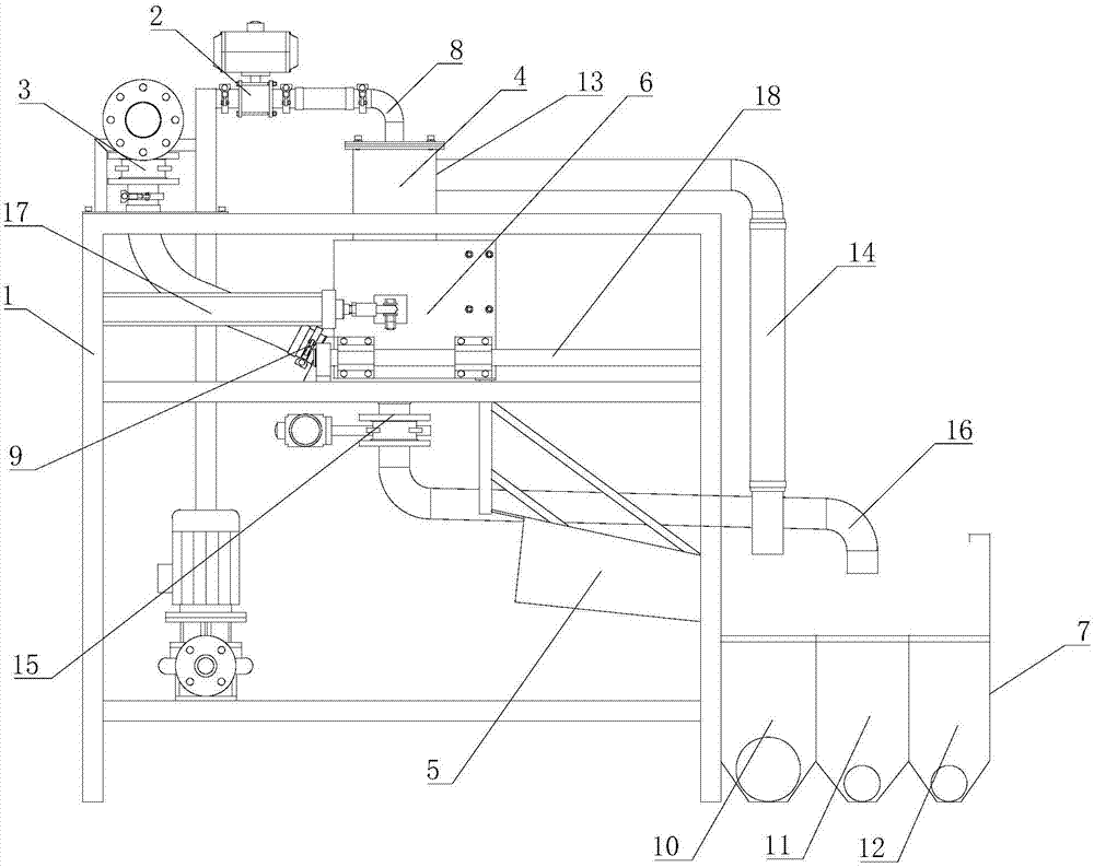
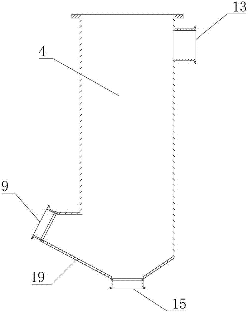
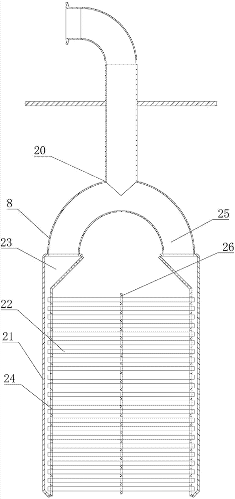
[0026] Such as figure 1 As shown, the fully automatic permanent magnet slurry iron remover includes a frame 1, a water inlet device 2, a slurry inlet device 3, a working chamber 4, a water outlet device 5, an iron removal device 6, and a slurry tank 7; the described work The cavity 4 is fixedly installed on the frame 1, and a medium cage 8 is arranged inside it; the water inlet device 2 is connected with the medium cage 8; the slurry feeding device 3 is connected with the working cavity 4 The slurry inlet 9 on the top is connected; the slurry tank 7 includes a slurry outlet tank 10, a slurry return tank 11, and an iron discharge tank 12; the iron removal device 6 can be installed on the frame 1 in a horizontal and linear reciprocating manner and Placed on the outside of the working chamber 4 to cooperate with the working chamber 4 to absorb iron filings in the slurry; the working chamber 4 is provided with a slurry outlet 13 to drain to the slurry outlet 10 through a slurry ou...


PUM


Abstract

The invention provides a full-automatic permanent magnetic machine for removing iron in slurry. The full-automatic permanent magnetic machine comprises a rack, a water inlet device, a slurry inlet device, a working cavity, a water passing device, an iron removing device and a slurry tank, wherein the working cavity is fixedly mounted on the rack; a medium cage is arranged inside the working cavity; the water inlet device is connected with the medium cage; the slurry inlet device is connected with a slurry inlet arranged on the working cavity; the slurry tank comprises a slurry outlet tank body, a slurry return tank body and an iron discharging tank body; the iron removing device mounted on the rack in a horizontal linear reciprocating motion manner, positioned on the outer side of the working cavity, and used for adsorbing iron filings in the slurry by cooperating with the working cavity; a slurry outlet is arranged on the working cavity; the slurry is drained to the slurry outlet tank body through a slurry outlet pipe; a slag discharging port is arranged on the working cavity and guided to the slurry tank through a slag discharging pipe; a fluid in the slag discharging pipe is drained to the slurry return tank body or the iron discharging tank body through the water passing device fixedly mounted on the iron removing device; and the water passing device performs reciprocating motion along with the iron removing device. The full-automatic permanent magnetic machine has the advantages of being simple in structure, high in productivity and low in failure rate.

Description

technical field [0001] The invention relates to the technical field of slurry iron removal equipment, in particular to a fully automatic permanent magnetic slurry iron removal machine. Background technique [0002] At present, many raw materials in industries such as ceramics and abrasives are in liquid form, because these raw materials themselves contain or are mixed with some ferromagnetic substances through processes such as mining, processing, transportation, etc., and these magnetic substances are very important for the above industries. Raw materials are only permitted in limited quantities or not at all. Therefore, the above-mentioned fluid raw materials need to be screened out by various iron removers in the previous process of the production process. [0003] At present, the working cavity of the slurry iron remover is set together with the slurry inlet, the slurry return port, and the iron discharge port, which leads to the crowded installation of the controlled v...

Claims


Application Information

Patent Timeline
Patent Type & Authority Applications(China)
IPC IPC(8): B03C1/10B03C1/02B08B3/02
CPCB03C1/02B03C1/10B08B3/02
Inventor 杜兴良杜迎昆杜习营
Owner 新乡市胜宇机电有限公司
Why Eureka
Try Eureka