Door for vehicle
A technology for car doors and vehicles, which is applied in the field of car doors, can solve the problems of increasing the size of reinforcement components and increasing the weight of car doors, etc., and achieve the effect of suppressing the increase and suppressing the weight of car doors
- Summary
- Abstract
- Description
- Claims
- Application Information
AI Technical Summary
Problems solved by technology
Method used
Image

Examples
no. 1 approach
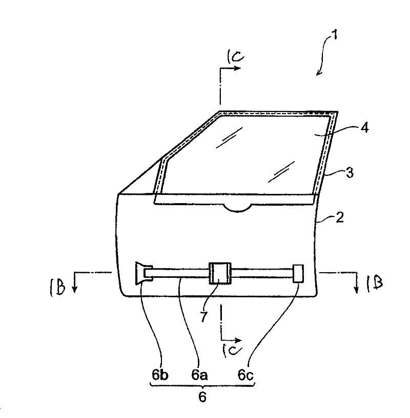
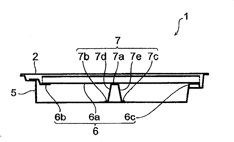
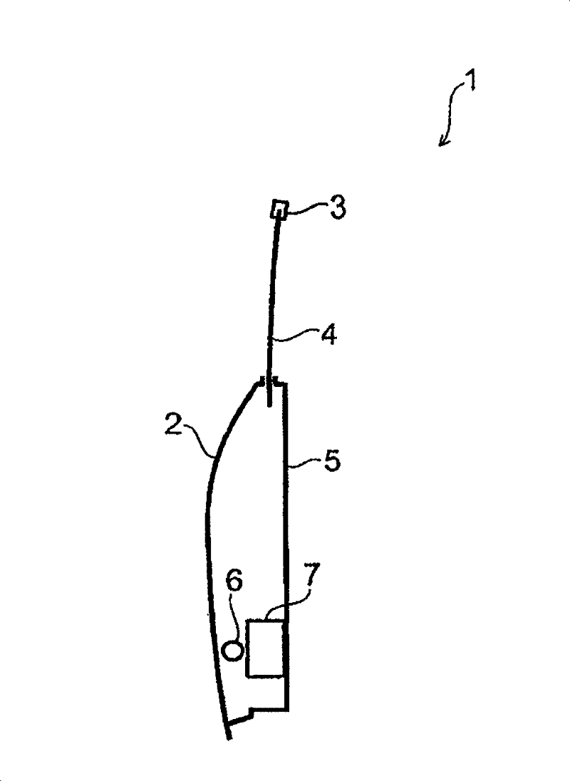
[0100] First, refer to Figures 1A to 1C The structure of the vehicle door according to the first embodiment of the present invention will be described. Figure 1A is a schematic diagram showing a vehicle door according to the first embodiment of the present invention viewed from the inner surface side. exist Figure 1A In , the inner panel is omitted to clearly show the characteristic parts of this embodiment. Figure 1B for along Figure 1A The door end view of the 1B-1B line. Figure 1C for along Figure 1A Door end view of line 1C-1C.
[0101] Figures 1A to 1C The illustrated vehicle door 1 comprises an outer panel 2 , a door frame 3 , a door glass 4 , an inner panel 5 , a side impact beam 6 and a support member 7 .
[0102] The outer panel 2 forms the outer surface of the vehicle door 1 . The outer panel 2 constitutes a part of the vehicle body. The door frame 3 is arranged on the outer panel 2 . When the window is closed, the outer panel 2 and the door frame 3 cov...
no. 2 approach
[0115] Then, will refer to Figures 4A to 4C The structure of a vehicle door according to a second embodiment of the present invention will be described. Figure 4A is a schematic diagram showing a vehicle door according to a second embodiment of the present invention viewed from the inner surface side. exist Figure 4A In , the inner panel is omitted to clearly show the characteristic parts of this embodiment. Figure 4B for along Figure 4A The door end view of the 4B-4B line. Figure 4C for along Figure 4A Door end view of line 4C-4C.
[0116] Figures 4A to 4C The vehicle door 1A shown differs from the vehicle door 1 in the first embodiment in that the vehicle door 1A comprises a support member 7A instead of the support member 7 . Since other parts of the configuration of the vehicle door 1A are the same as those of the vehicle door 1, their description will be omitted.
[0117] Such as Figure 4B and 4C As shown, the support member 7A differs from the support m...
no. 3 approach
[0122] Next, we will refer to Figures 5A to 5C The structure of a vehicle door according to a third embodiment of the present invention will be described. Figure 5A is a schematic diagram showing a vehicle door according to a third embodiment of the present invention viewed from the inner surface side. exist Figure 5AIn , the inner panel is omitted to clearly show the characteristic parts of this embodiment. Figure 5B for along Figure 5A The door end view of the 5B-5B line. Figure 5C for along Figure 5A The door end view of the 5C-5C line.
[0123] Figures 5A to 5C The vehicle door 1B shown differs from the vehicle door 1 in the first embodiment in that the vehicle door 1B further comprises a load bearing member 8 and comprises a support member 7B instead of the support member 7 . The rest of the structure of the door 1B is the same as that of the door 1 . Therefore, their description will be omitted.
[0124] The bearing member 8 is a flat plate extending in ...
PUM
 Abstract
Description
Claims
Application Information
 - R&D
- Intellectual Property
- Life Sciences
- Materials
- Tech Scout
- Unparalleled Data Quality
- Higher Quality Content
- 60% Fewer Hallucinations
Browse by: Latest US Patents, China's latest patents, Technical Efficacy Thesaurus, Application Domain, Technology Topic, Popular Technical Reports.
© 2025 PatSnap. All rights reserved.Legal|Privacy policy|Modern Slavery Act Transparency Statement|Sitemap|About US| Contact US: help@patsnap.com