A bidirectional level conversion circuit
A technology for converting circuits and levels, applied in the direction of logic circuit connection/interface layout, etc., can solve the problems of affecting development and production progress, long delivery cycle, high cost, etc., to reduce production costs and business risks, strong driving ability, Strong anti-interference ability
- Summary
- Abstract
- Description
- Claims
- Application Information
AI Technical Summary
Problems solved by technology
Method used
Image

Examples
Embodiment 1
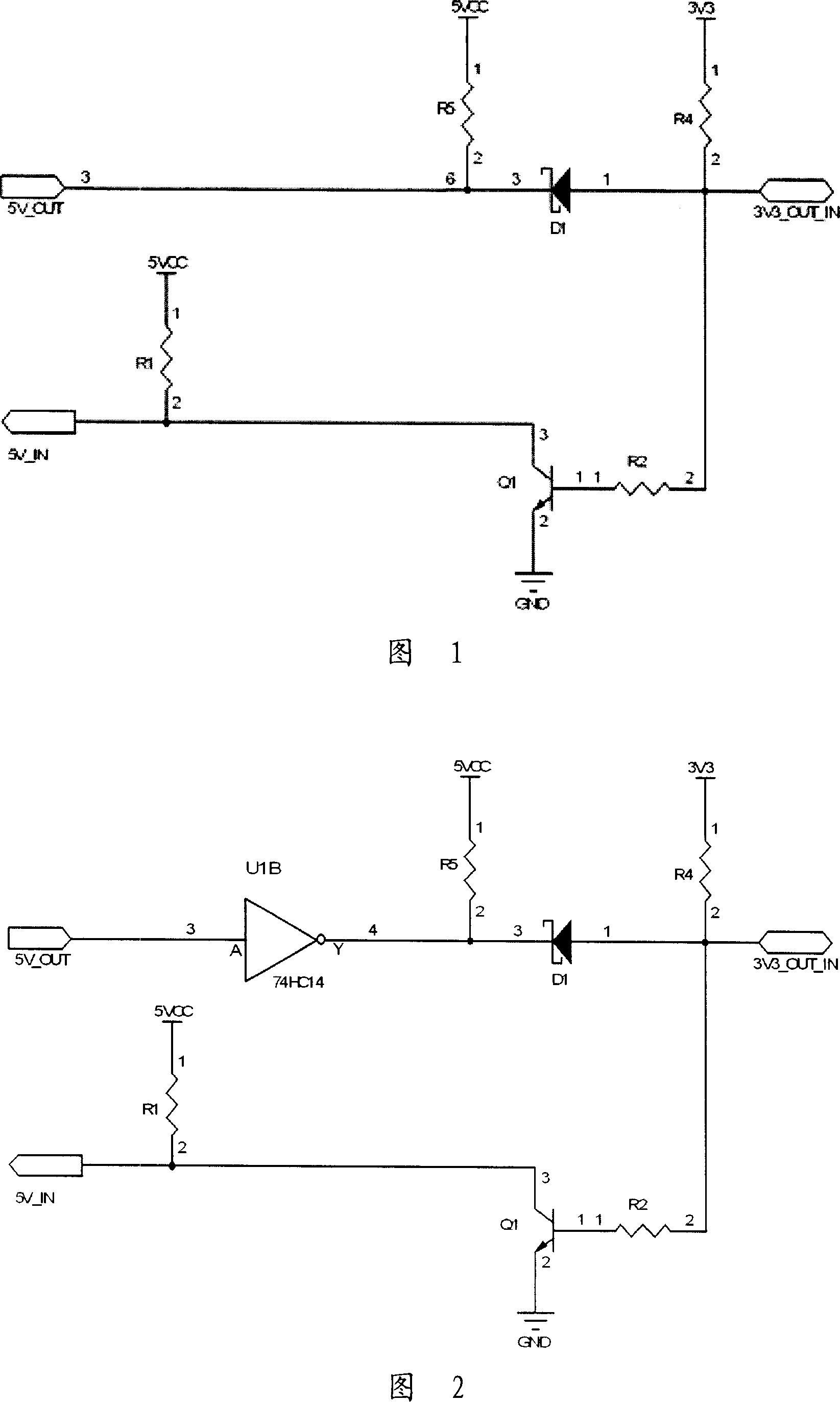
[0024] Referring to Fig. 1, the level conversion circuit diagram of Embodiment 1 is given.
[0025] This embodiment implements level conversion between 3.3V bidirectional port and 5V input port and output port, including triode Q1, Schottky diode D1, resistor R1, resistor R2, resistor R4 and resistor R5. The base and collector of the transistor Q1 are respectively connected to the 3.3V bidirectional port, which is the 3V3_OUT_IN port, and the 5V input port, which is the 5V_IN port, and the emitter of the transistor Q1 is grounded; the positive and negative electrodes of the diode D1 are respectively connected to the 3.3V bidirectional port, which is the 3V3_OUT_IN port and the 5V output port Namely the 5V_OUT port.
[0026] The working principle of this embodiment is as follows: when the 3V3_OUT_IN port is used as an input, if the 5V_OUT port outputs a high level, the diode D1 is cut off, and the 3V3_OUT_IN port is pulled up to a high level by the resistor R4; if the 5V_OUT po...
Embodiment 2
[0030] In order to overcome the above shortcomings, on the basis of embodiment 1, embodiment 2 is proposed, as shown in FIG. 2 .
[0031] This embodiment realizes the level conversion between the 3.3V bidirectional port 3V3_OUT_IN and the 5V input port 5V_IN and the output port 5V_OUT, including transistor Q1, Schottky diode D1, 7 4HC14 inverter U1B and resistor R1, resistor R2, resistor R4 and resistor R5. The base and collector of the transistor Q1 are respectively connected to the 3V3_OUT_IN port and the 5V_IN port, and the emitter of the transistor Q1 is grounded; the 5V_OUT port is connected to the 3V3_OUT_IN port through the inverter U1B and the diode D1, and the input terminal of the inverter U1B is connected to the 5V_OUT port, and the output terminal Connect the cathode of diode D1; connect the anode of diode D1 to the 3V3_OUT_IN port.
[0032] The working principle of this embodiment is as follows: when the 3V3_OUT_IN port is an input, if the 5V_OUT port outputs a h...
Embodiment 3
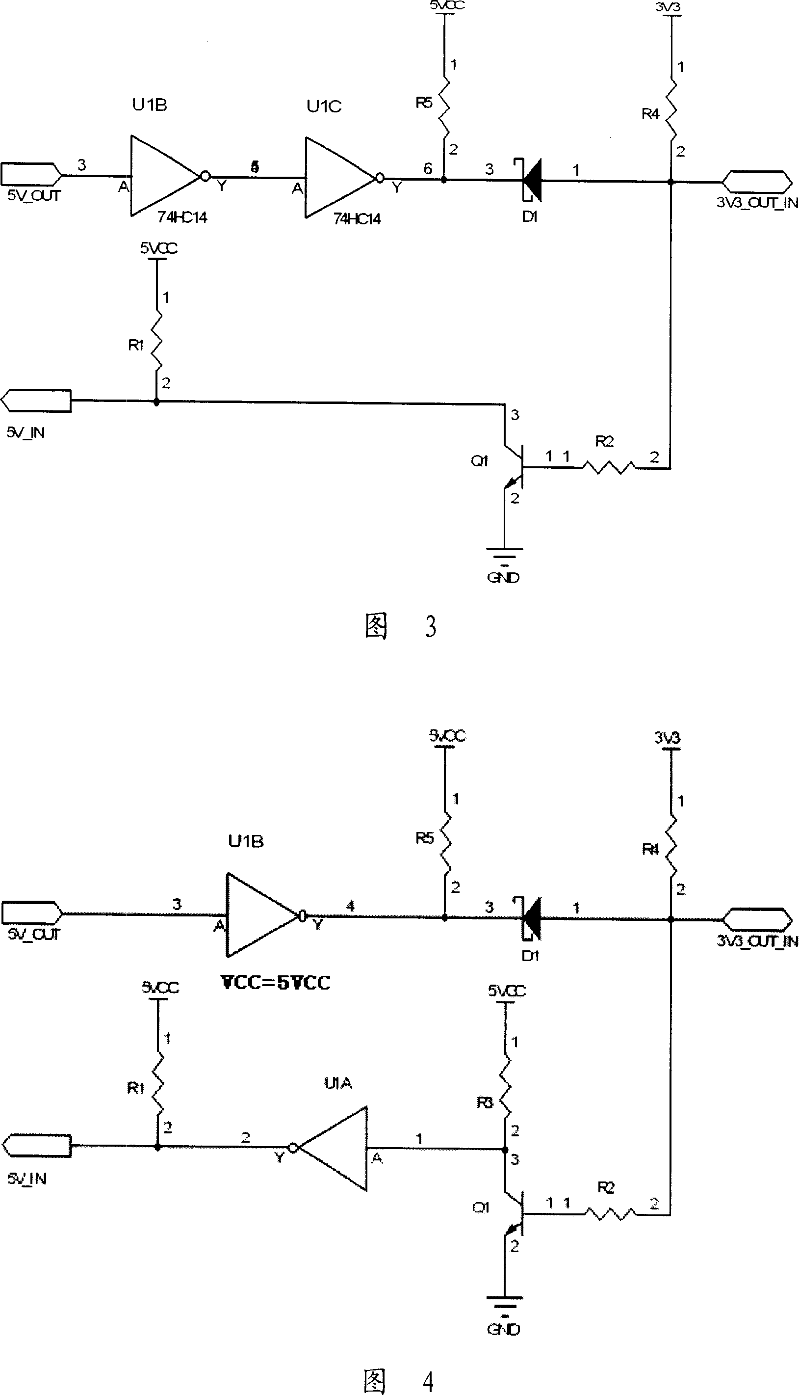
[0036] On the basis of the above embodiments, a further improvement scheme is proposed. As shown in Figure 3, an inverter U1C is added between the output terminal of the inverter U1B and the cathode of the diode D1. The inverter uses a 74HC14 device to receive the level signal output by U1B and output it to The cathode of diode D1. The working principle of this circuit is similar to that of Embodiment 2, so it will not be described in detail.
[0037] The 5V_OUT port output to the 3V3_OUT_IN port input in Embodiment 2 is reversed, while the 5V_OUT port output to the 3V3_OUT_IN port input in this embodiment is in the same direction. Compared with the above embodiment, this embodiment has stronger driving capability and stronger anti-interference ability.
PUM
 Abstract
Description
Claims
Application Information
PatSnap Eureka turns technology decisions into work you can execute. Powered by our Innovation Knowledge Graph, it runs expert workflows across engineering, life sciences, materials and intellectual property. Get your review-ready output in minutes.


