Communication control unit

A communication control and communication device technology, applied in telephone communication, interconnection devices, digital transmission systems, etc., can solve problems such as inability to use linkage systems

Inactive Publication Date: 2007-07-11
HITACHI LTD
View PDF1 Cites 3 Cited by
  • Summary
  • Abstract
  • Description
  • Claims
  • Application Information

AI Technical Summary

Problems solved by technology

In this case, even if the information system is advanced, the advanced linkage system cannot be used because the telephone system is old

Method used


Image

  • Communication control unit
  • Communication control unit
  • Communication control unit

Examples


Embodiment 1

[0035] In this embodiment, first, the physical structure, logical structure, operation outline of the telephone adapter of the present invention, and an example of an actual network connection method of a corporate office using the adapter will be described. Next, a specific application example of the telephone adapter of the present invention will be described using a sequence diagram, an example of a display on a PC, and an example of a message.

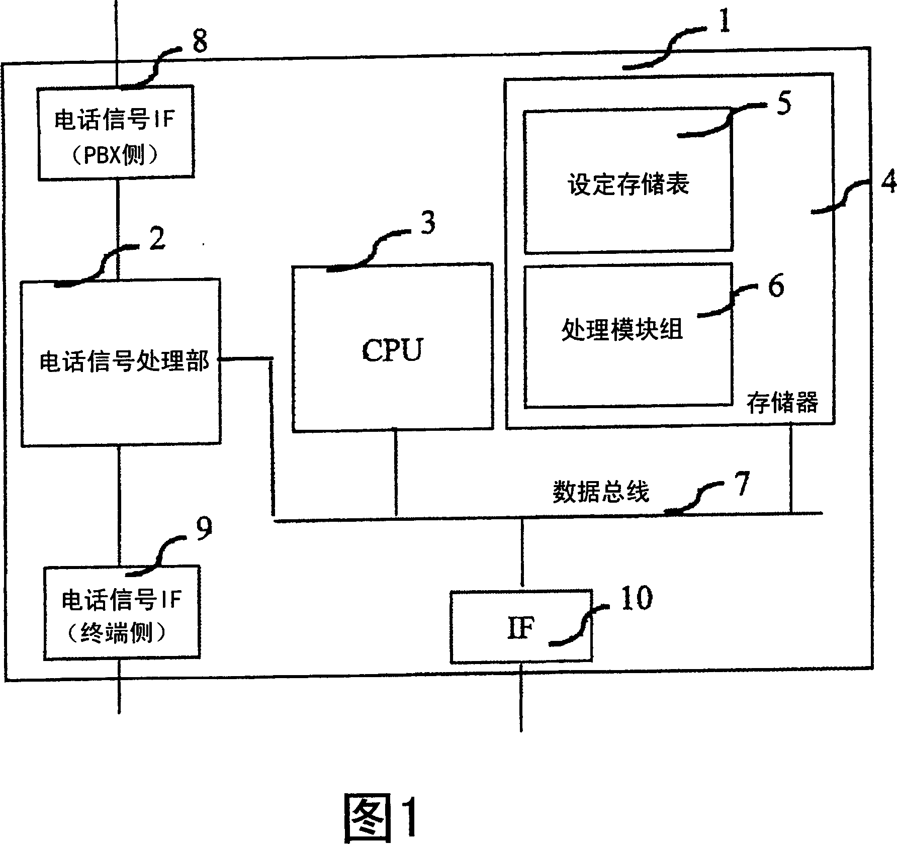
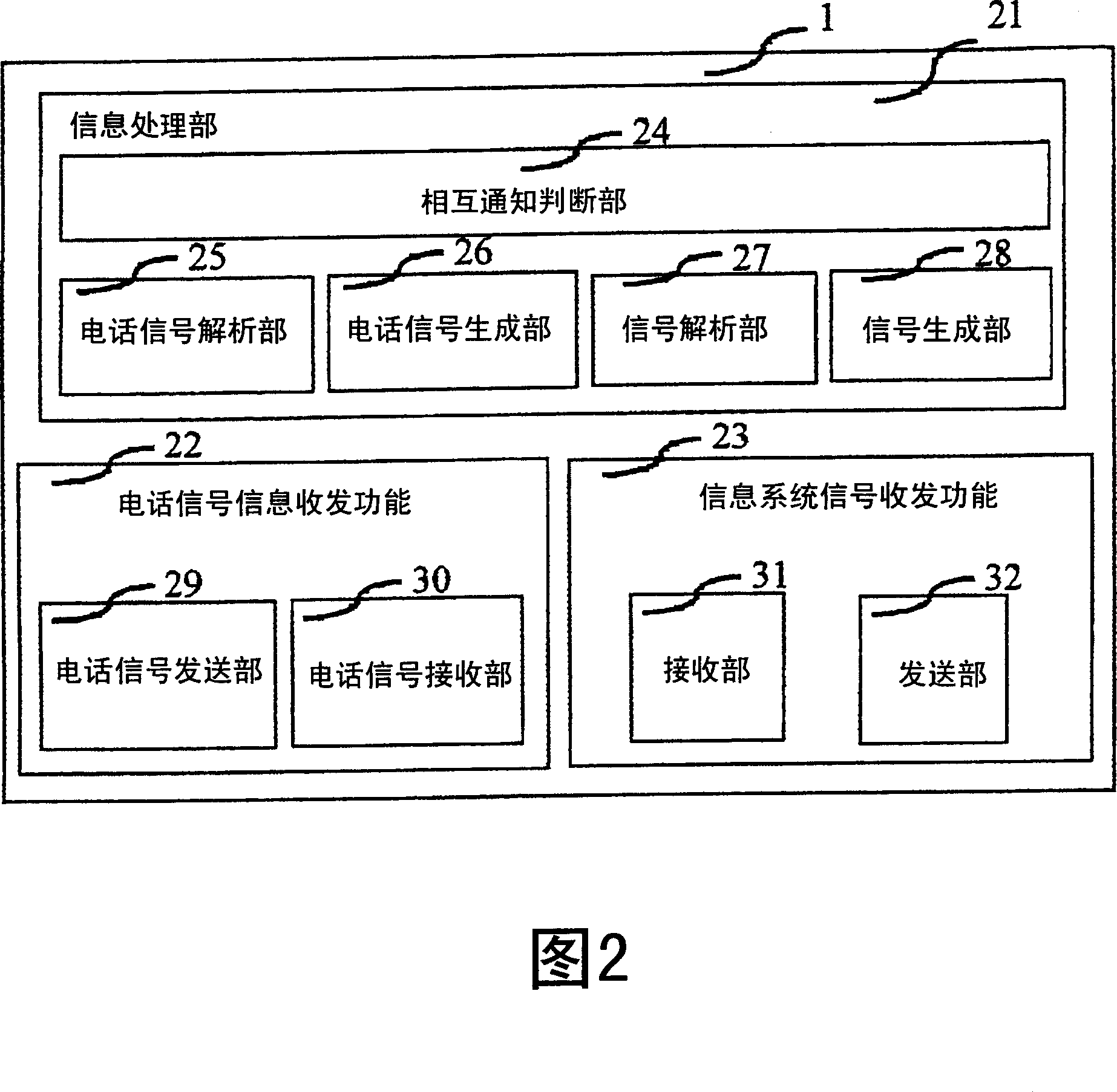
[0036] FIG. 1 shows an example of the physical structure of the telephone adapter of the present invention. In addition, FIG. 2 shows a functional block diagram of the telephone adapter of the present invention. The functional block diagram of FIG. 2 is a diagram showing a logical functional structure, and each functional block may be configured by either software or hardware.

[0037] If the functional block shown in FIG. 2 is realized by software, its processing content is stored in the processing module group 6 in the memory 4 ...

Embodiment 2

[0064] 10 and 11 are examples of the case where the operation example of FIG. 7 is realized by different types of telephone adapters. In this example, the telephone adapter does not activate the action trigger by receiving the telephone signal, but configures the receiver sensor 901 next to the hook key 902 of the telephone as shown in the lower figure of Figure 10, and has the ability to move up and down the hook key through the receiver 903. At the same time, the sensor also perceives the structure of the movement, and the movement trigger is activated by the up and down of the receiver. In addition, in accordance with this structure, the physical structure of the telephone adapter is also in the form of the upper diagram of FIG. 10 . The difference from FIG. 1 is that instead of the telephone signal processing unit 2, telephone signal IF (PBX side) 8, and telephone signal IF (terminal side) 9 shown in FIG. 1, a receiver sensor 151 is arranged to perform a function equivalen...

Embodiment 3

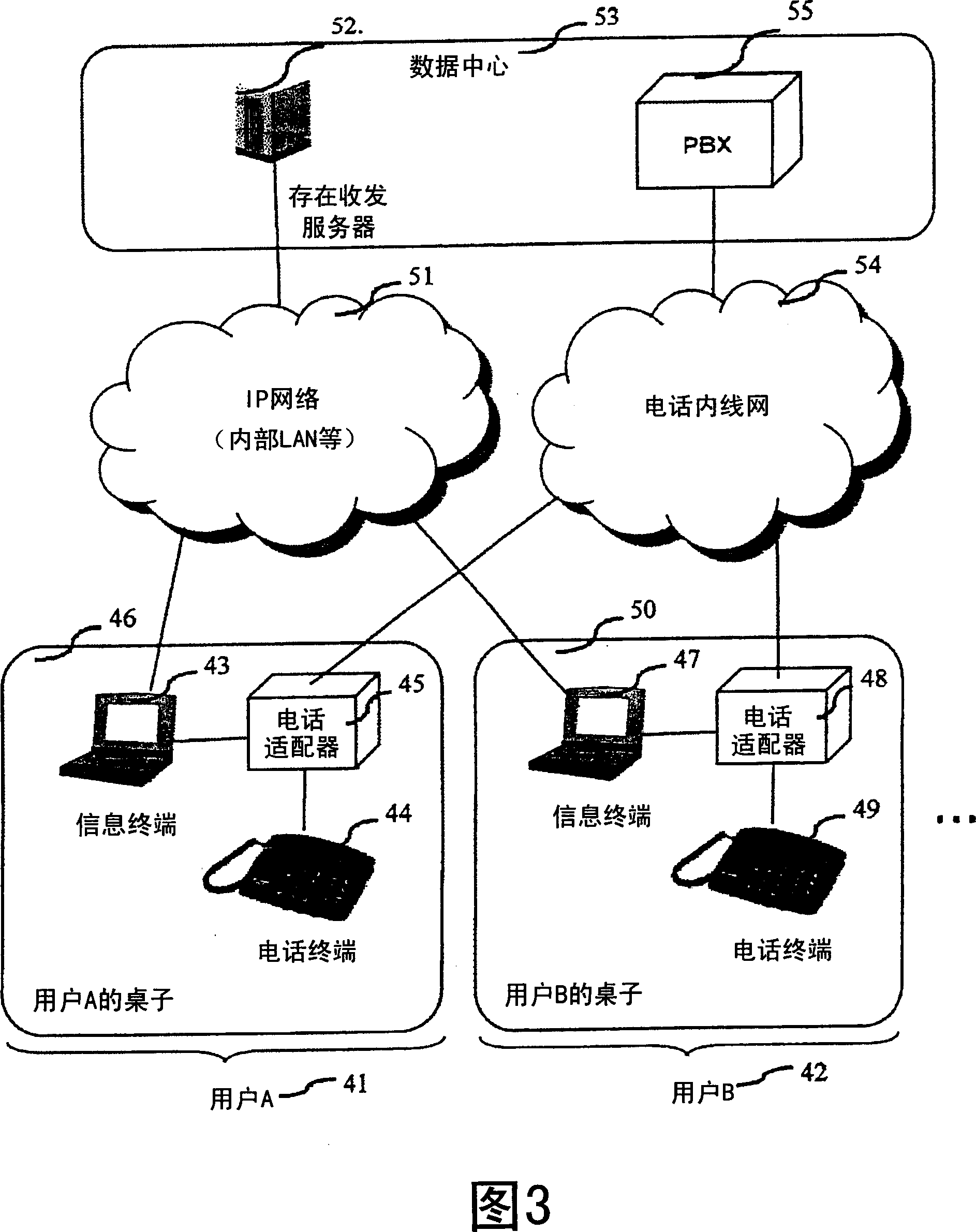
[0070] Fig. 12 is a sequence diagram showing a second application example of the present invention. In Fig. 12, each telephone adapter sends the situation to the existence transceiver server when the telephone terminal in charge of itself has a call, and the users around can judge which telephone terminal's bell is ringing at present. This example will be described in order. In addition, this example is an example of a network connection system as shown in FIG. 4 . In this example, the telephone adapter generates an action trigger from the telephone signal side in the form shown in FIG. 5, and operates on the condition of "when there is a telephone call".

[0071] In this example, first, in step 181 , the user B's information terminal logs into the presence / reception server 52 . Then subscribe to your own floor ID. For example, if your own room is Room 301 on 3F, you need to subscribe to its ID. Thereby, it is possible to receive presence information on which part the phon...


PUM


Abstract

An extension telephone using an ordinary telephone circuit cannot be coordinated with a data terminal connected by an IP network. An extension telephone using an ordinary telephone circuit has none of the convenient functions of an IP telephone, such as implementing outgoing / incoming call data management and telephone book management on a PC. A telephone terminal using an ordinary telephone circuit and a data terminal in an IP network can however be coordinated by reflecting telephone calls and call signal details in an IP network by means of a telephone adapter which can send and receive IP network data and call signals using IP network data as a trigger. A user of an ordinary telephone system can easily coordinate a telephone with a data terminal, and even if there is a 'modernization time lag' between the data system and telephone system, or the IP telephone system is introduced gradually, an environment is created whereby all users can make maximum use of coordination between the data system and telephone system.

Description

technical field [0001] The present invention relates to the acquisition of telephone state and the method of telephone setting. Background technique [0002] In recent years, research and development of a state grasping technology between users using a concept called "presence" has been actively carried out. The so-called "presence", as its name implies, is the "presence" of each user for notifying other users, and specifically, it means the current position and current state of each user or communication device, and various other types of own existence. information. By notifying other users of this "existence" in real time, it is possible to grasp each other's current status, for example, it is possible to judge "the other party is busy now, so please contact me later", or "the other party is out now, so please contact the other party's mobile phone", etc. . These existing concepts and communication technologies are developed from IM (Instant messaging: Instant Messaging...

Claims


Application Information

Patent Timeline
Patent Type & Authority Applications(China)
IPC IPC(8): H04L12/58H04L29/06
CPCH04M7/0012
Inventor 宫田辰彦小高浩山田真理子
Owner HITACHI LTD
Why Eureka
Try Eureka