Thoracic aortic covered stent

a stent and aortic valve technology, applied in the field of medical devices, can solve the problems of high mortality rate, heavy wounds to patients, and dangerous diseases, and achieve the effect of avoiding the “turnover effect”

Active Publication Date: 2018-07-03
LIFETECH SCI (SHENZHEN) CO LTD
View PDF7 Cites 4 Cited by
  • Summary
  • Abstract
  • Description
  • Claims
  • Application Information

AI Technical Summary

Benefits of technology

[0008]An object of the present invention is to provide a thoracic aortic covered stent which prevents a metal wire in a bare stent segment from overturning towards the vessel wall.
[0017]In the thoracic aortic covered stent according to the embodiment of the present invention, along the direction from the lesser curvature side region to the large lesser curvature side region, the wave height of the bare wave-shaped ring is gradually decreased, and the waveform fillet is gradually increased.
[0019]The thoracic aortic covered stent provided by the present invention, at near the lesser curvature side with a relatively small radius of curvature, has a connecting assembly rigidly connecting the bare stent segment and the covered stent segment, and through the constraints thereof, the bare stent segment can be effectively prevented from overturning towards the vessel wall during the release process, so that the proximal end of the covered stent segment is securely apposed to the wall, thereby avoiding the “turnover” effect.

Problems solved by technology

The aortic aneurysm or aortic dissection, with mortality rate higher than 50% within 48 hours and higher than 85% within two weeks after the onset, is a very dangerous disease which has been a serious threat to human health.
The surgical treatments present great difficulty, are difficult operations, involve long operation time, often result in heavy wounds to patients, and have high mortality rates.
In addition, pipelines in the surgical field are numerous and have complex order and many anastomotic stomas, resulting in prolonging the operation time and correspondingly prolonging the cerebral ischemia time and extracorporeal circulation time, thereby increasing the operative mortality rates and complications (especially cerebral complications).
However, during the endovascular release process of the stent, the stent is pushed by a deployer at the distal end of the stent, and gradually released from the proximal end to the distal end; due to the flexible connection between the bare stent segment and the covered stent segment, the pushing force will probably cause the metal wire in the bare stent segment to overturn towards the vessel wall and to contact with the vessel wall, so that the proximal end of the covered stent segment may not be securely apposed to the wall, thereby resulting in the “turnover effect.
Once there is a “turnover” effect”, not only the metal wire overturned in the bare stent segment will damage the blood vessel, but also I type endoleak is easily generated between the stent and the blood vessel, namely due to the proximal end of the stent and the blood vessel being not completely enclosed, the blood continuously flows into the aortic aneurysm or the aortic dissection, thereby resulting in continually growing of the aneurysm cavity or the dissection cavity, and leading to the treatment failure and ultimately leading to serious consequences such as rupture.

Method used


Image

  • Thoracic aortic covered stent
  • Thoracic aortic covered stent
  • Thoracic aortic covered stent

Examples


Embodiment Construction

[0036]In order to understand the technical characteristics, the objects and the effects of the present invention more clearly, the specific implementation ways of the present invention will be described in detail with reference to the accompanying drawings.

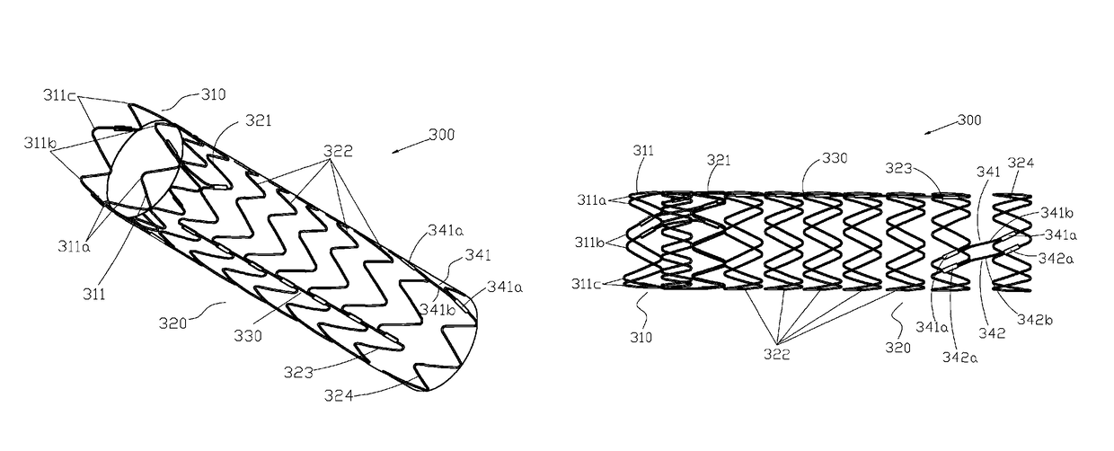
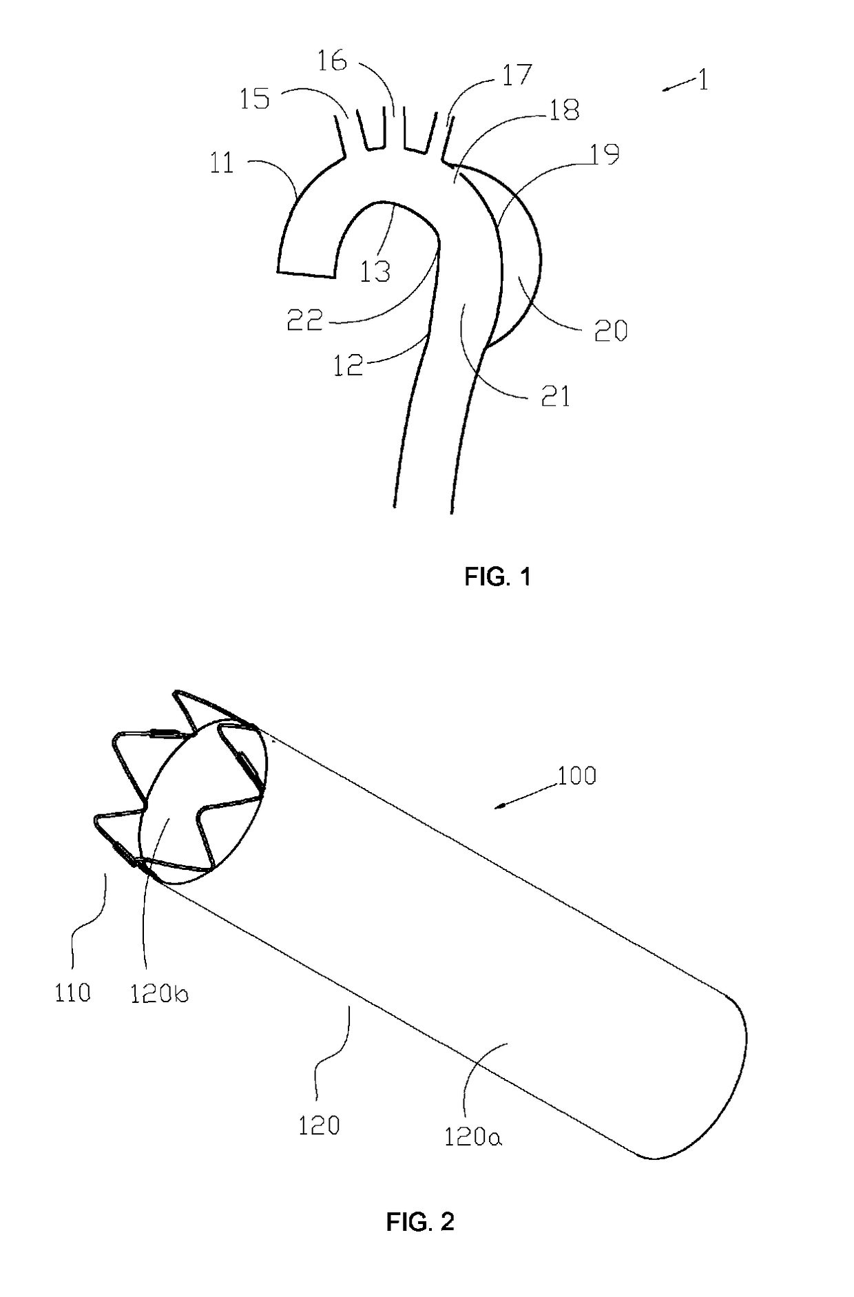
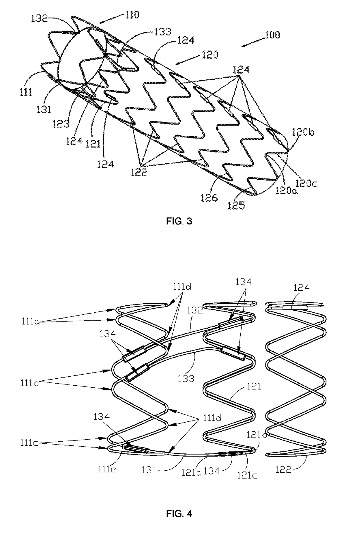
[0037]With reference to FIG. 2 and FIG. 3 a thoracic aortic covered stent 100 (hereinafter referred to as stent) of an embodiment of the present invention includes a bare stent segment 110 and a covered stent segment 120 along an axial direction from the proximal end to the distal end sequentially, and a connecting assembly for rigidly connecting the bare stent segment 110 and the covered stent segment 120.

[0038]The covered stent segment 120 includes a plurality of wave-shaped rings 121, 122, 123, 125 and 126, and a membrane 120a; the membrane 120a is fixed on the plurality of wave-shaped rings to connect the plurality of wave-shaped rings so as to enclose and form a lumen 120b with a vertical axis; when the stent is implanted int...


PUM


Abstract

The present invention relates to a thoracic aortic covered stent (100), comprising a bare stent segment (110) and a covered stent segment (120). The bare stent segment (110) comprises a bare wave-shaped ring (111); the covered stent segment (120) has a lesser curvature side region (100c), a greater curvature side region (100a), and two opposite intermediate regions (100b) located between the lesser curvature side region (100c) and the greater curvature side region (100a) respectively; and the covered stent segment (120) comprises a first proximal wave-shaped ring (121). The stent (100) further comprises a first connecting member (131), a first side connecting member (132) and a second side connecting member (133) all connected to the bare wave-shaped ring (111) and the first proximal wave-shaped ring (121), wherein the first connecting member (131) is arranged in the lesser curvature side region (100c), and the first side connecting member (132) and the second side connecting member (133) are arranged in the two intermediate regions (100b) respectively. The stent (100) when located near the lesser curvature side (22) with a relatively small radius of curvature has a connecting assembly rigidly connecting the bare stent segment (110) and the covered stent segment (120), and through the constraints thereof, the bare stent segment (110) can be effectively prevented from overturning towards the vessel wall during the release process, so that the proximal end of the covered stent segment (120) is securely apposed to the wall, thereby avoiding the “turnover” effect.

Description

TECHNICAL FIELD[0001]The present invention relates to the technical field of medical devices, in particular to a thoracic aortic covered stent.BACKGROUND OF THE PRESENT INVENTION[0002]Aortic diseases mainly include aortic dissection and aortic aneurysm; the aortic aneurysm is further divided into true aortic aneurysm and false aortic aneurysm. The aortic aneurysm or aortic dissection, with mortality rate higher than 50% within 48 hours and higher than 85% within two weeks after the onset, is a very dangerous disease which has been a serious threat to human health. With the advent of China's aging population trends, the incidence thereof will be constantly rising.[0003]Taking the thoracic aortic dissection as an example, as shown in FIG. 1, an aorta 1 includes an ascending aorta 11 connected to the heart, a descending aorta 12, and an aortic arch 13 between the two; the descending aorta 12 comprises a thoracic aorta 21 and an abdominal aorta (not shown in the figure); the aortic arch...

Claims


Application Information

Patent Timeline
Patent Type & Authority Patents(United States)
IPC IPC(8): A61F2/915A61F2/89A61F2/07A61F2/82
CPCA61F2/07A61F2/89A61F2/915A61F2002/075A61F2250/0039A61F2002/91508A61F2220/0058A61F2220/0075A61F2230/0067A61F2002/825A61F2002/8486A61F2002/91516
Inventor WANG, YONGSHENGLIU, CAIPINGZHANG, DEYUAN
Owner LIFETECH SCI (SHENZHEN) CO LTD
Why Eureka
Try Eureka