
a floating breakwater

A floating breakwater and floating tank technology, applied in the field of marine engineering equipment, can solve the problems of reduced wave-absorbing capacity, complex structure, and limited breakwater width, and achieve the effects of easy disassembly and replacement, enhanced wave-absorbing performance, and high safety performance

Active Publication Date: 2020-06-09
JIANGSU UNIV OF SCI & TECH
View PDF6 Cites 0 Cited by
  • Summary
  • Abstract
  • Description
  • Claims
  • Application Information

AI Technical Summary

Problems solved by technology

Chinese invention patent (CN201310253105.3) "A perforated box type floating breakwater with built-in buoyancy unit", the breakwater has the following defects: 1. When the perforated box structure is damaged, the internal buoyancy unit easily escapes from the perforated box, causing the buoyancy 2. The floating unit moves staggered inside the hole box, and the load on the floating breakwater in the direction vertical to the water surface is small. In the case of large wave height, the breakwater is prone to over-wave, reducing its Wave dissipation capacity; 3. The breakwater is limited in width, and the wave dissipation effect on long-period waves is poor; 4. The structure is relatively complicated, which is not convenient for offshore construction and later replacement and maintenance

Method used


Image

  • a floating breakwater
  • a floating breakwater
  • a floating breakwater

Examples


Embodiment Construction

[0022] The present invention will be described in further detail below in conjunction with the accompanying drawings.

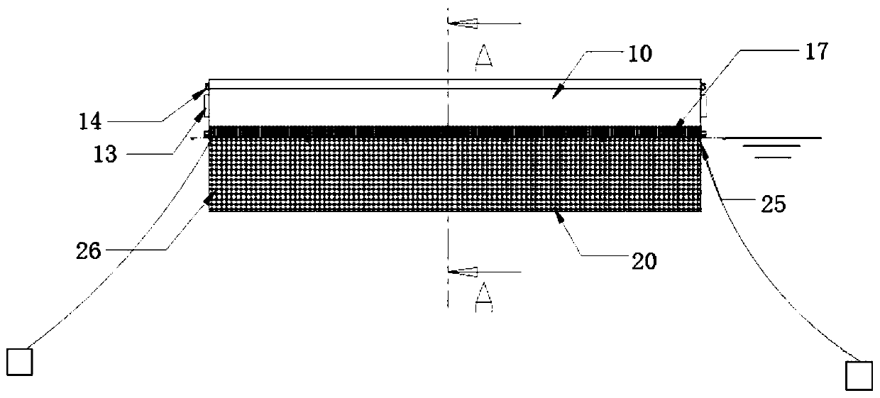
[0023] figure 1 It is a structural schematic diagram of the floating tank of an embodiment of the floating breakwater of the present invention. The invention consists of figure 1 The shown buoyant tank units are connected by connecting devices and then moored in the working sea area to form floating breakwaters. The length of the floating breakwater is determined by the number of pontoon units, which is theoretically unlimited.

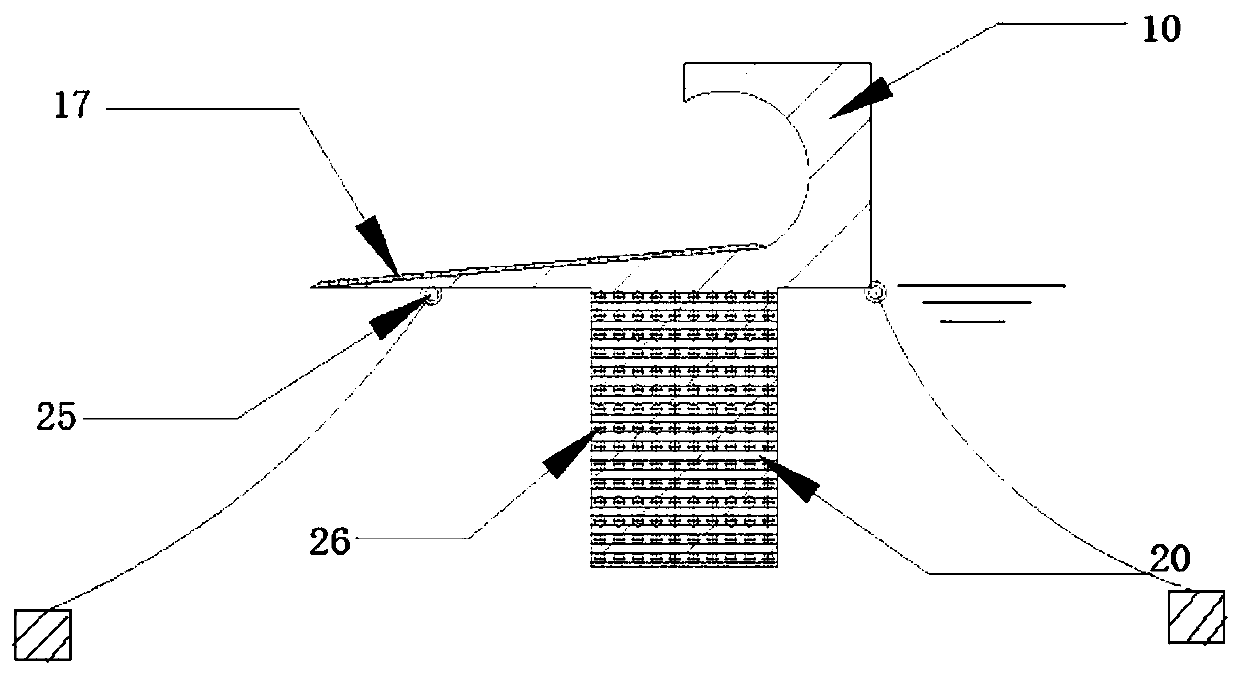
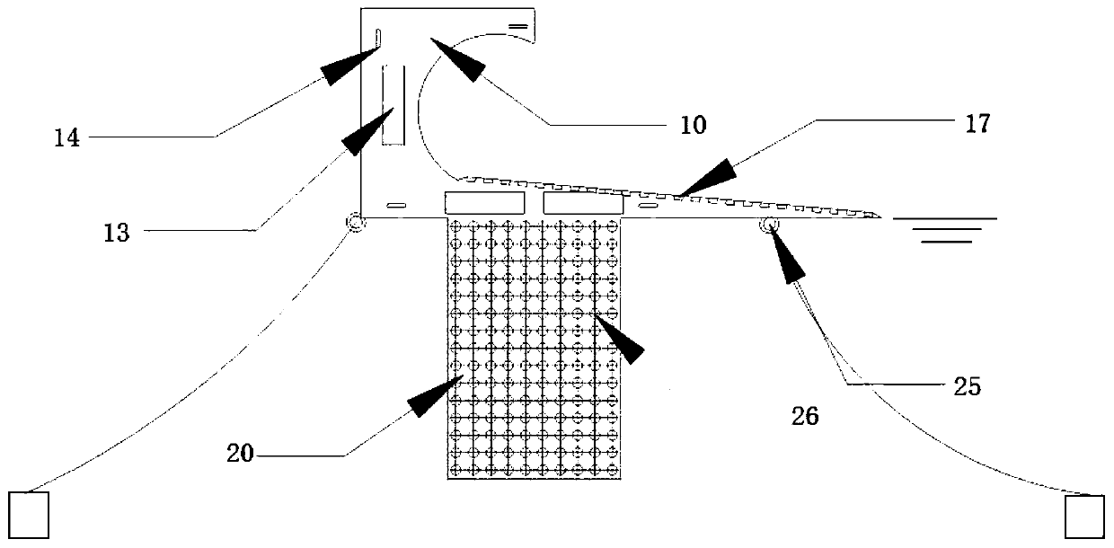
[0024] The buoy box includes: an upper floating body 10, a lower floating body 20, a crash pad 13, a connecting fairlead 14, a mooring fairlead 25, a wave-dissipating hole 26, and a block energy dissipation device 17. The upper floating body 10 and the lower floating body 20 are consolidated into one body.

[0025] The upper floating body 10 of the buoyancy tank is made of steel material, and is a groove-shaped structure with a l...


PUM


Abstract

The invention discloses a floating breakwater. The floating breakwater comprises a plurality of floating boxes which are connected to one another by connecting devices, wherein each floating box comprises an upper floating body and a lower floating body which are in contact from top to bottom and are fixedly arranged; the upper floating body is of a tortuous slope-shaped groove type steel structure, and a plurality of block-shaped energy dissipating devices are arranged on the inward bending surface of the groove of the upper floating body; the lower floating body is a rectangular body made of a high-strength polypropylene material, and a plurality of wave dissipating holes which are perforated and staggered are formed in the lower floating body; and the floating banks are provided with mooring guide rope holes which are used for connecting guide ropes so as to moor the floating boxes in water. The floating breakwater has the beneficial effects that the floating breakwater has a good wave dissipating effect under terrible ocean environments and long-period waves and is simple in structure; and the width of the breakwater is unlimited due to adoption of modular assembly, thereby facilitating offshore construction and later maintenance.

Description

technical field [0001] The invention belongs to the technical field of marine engineering equipment, and in particular relates to a floating breakwater. Background technique [0002] The marine environment is complex, and offshore floating structures are simultaneously affected by wind, wave, and current loads, especially wave loads, which seriously affect the safety of offshore floating structures and the comfort of staff. In order to weaken the wave load on the floating structures on the sea, floating breakwaters are usually arranged around the floating structures to absorb and consume wave energy to reduce the wave force. Floating breakwaters are usually wave-resistant facilities made of metal, reinforced concrete and plastic materials and mooring equipment. The wave-dissipating floating body is composed of a box or floating row with a certain draft. The box or floating row is connected to the anchor chain fixed on the seabed at one end and floats on the water. Compared...

Claims


Application Information

Patent Timeline
Patent Type & Authority Patents(China)
IPC IPC(8): E02B3/06
CPCE02B3/062Y02A10/11
Inventor 凌宏杰王志东姚震球窦朋王海星
Owner JIANGSU UNIV OF SCI & TECH
Learn More