Communication apparatus and control method thereof

a communication apparatus and control method technology, applied in power management, high-level techniques, wireless commuication services, etc., can solve the problems of consuming power for maintaining communication in a permanent connection, battery driving time tends to be shorter when communication is utilized,

Active Publication Date: 2018-07-03
CANON KK
View PDF7 Cites 2 Cited by
  • Summary
  • Abstract
  • Description
  • Claims
  • Application Information

AI Technical Summary

Benefits of technology

[0008]According to one aspect of the present invention, there is provided a communication apparatus comprising: a first transmission unit configured to transmit, to a relay apparatus, identification information for identifying a push message to be transmitted to the communication apparatus; a reception unit configured to receive, from the relay apparatus, a push message transmitted by the relay apparatus after the first transmission unit transmits the identification information to the relay apparatus; and a control unit configured to perform a process for switching an operation mode of the communication apparatus from a first operation mode to a second operation mode lower in power consumption than the first operation mode after the first transmission unit transmits the identification information to the relay apparatus.
[0011]According to another aspect of the present invention, there is provided a control method of a communication apparatus comprising: transmitting, to a relay apparatus, identification information for identifying a push message to be transmitted to the communication apparatus by using a first transmission unit; receiving, from the relay apparatus, a push message transmitted by the relay apparatus after the first transmission unit transmits the identification information to the relay apparatus; and performing a process for switching an operation mode of the communication apparatus from a first operation mode to a second operation mode lower in power consumption than the first operation mode after the first transmission unit transmits the identification information to the relay apparatus.

Problems solved by technology

In an electronic apparatus driven by an internal battery, however, a battery driving time tends to be shorter when communication is utilized.
For example, when the client is an electronic apparatus such as a digital camera, power for maintaining communication in a permanent connection is consumed, in addition to power consumed for a shooting operation as a primary function.

Method used


Image

  • Communication apparatus and control method thereof
  • Communication apparatus and control method thereof
  • Communication apparatus and control method thereof

Examples


first embodiment

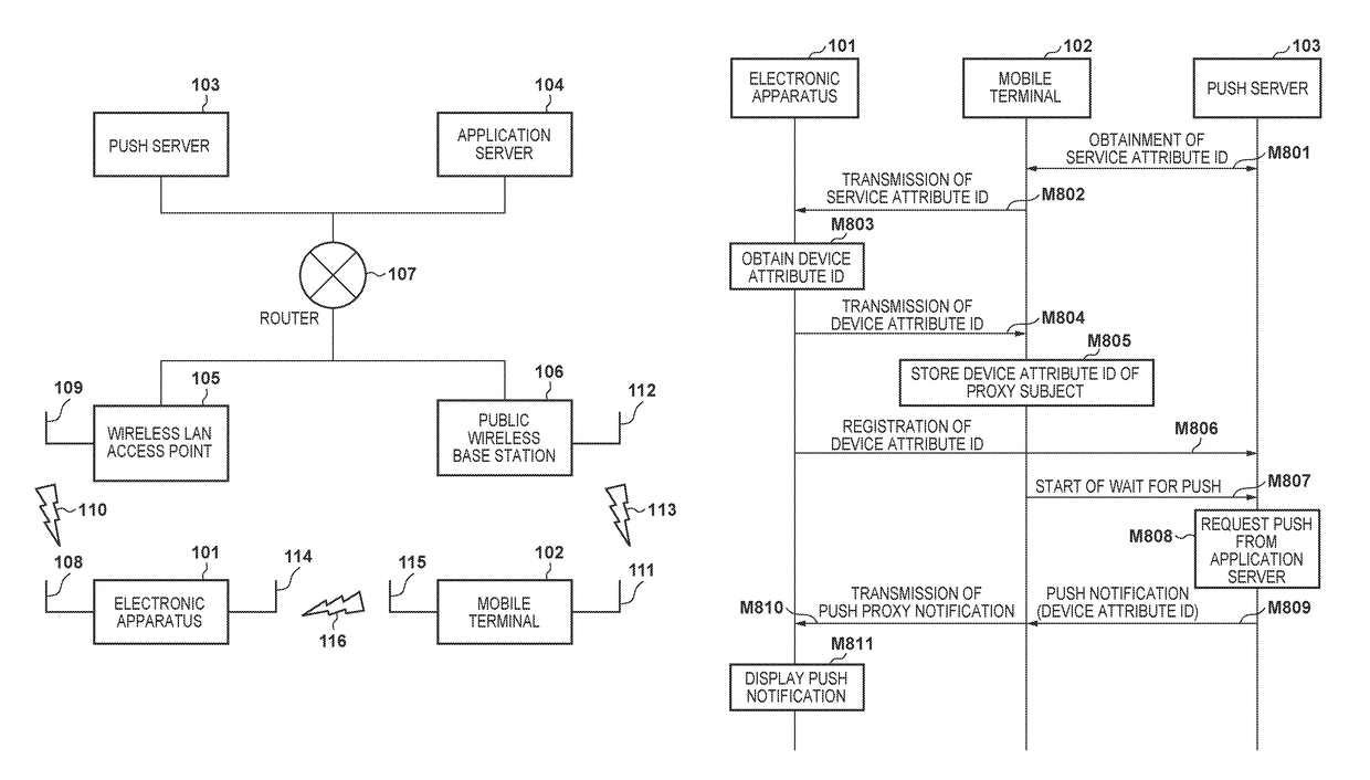
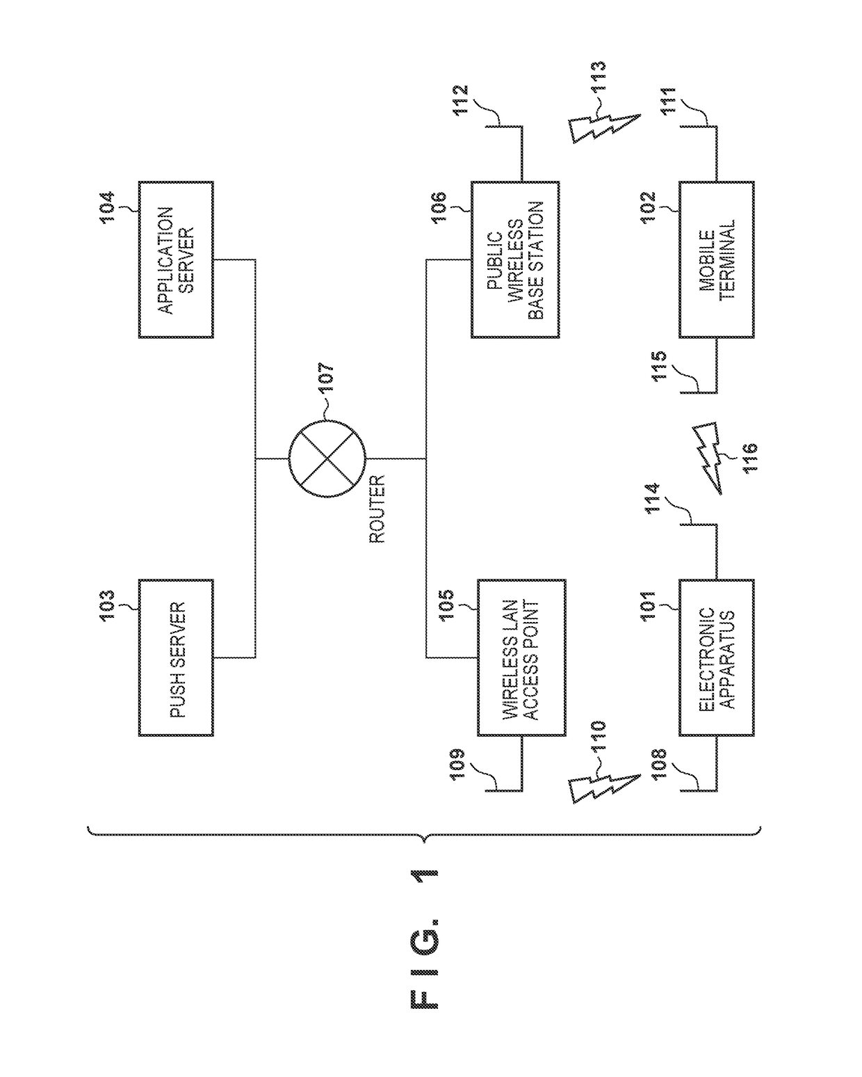
[0031]FIG. 1 is a block diagram showing an example of the arrangement of a communication system. An electronic apparatus 101 is an example of an apparatus that can function as a communication apparatus such as a digital camera, a projector, a surveillance camera, a DTV (Digital TV), or a printer. The electronic apparatus 101 performs Internet communication via a network by a wireless or wired LAN. A mobile terminal 102 is an example of an apparatus that can function as a communication apparatus such as a smartphone or a tablet. The mobile terminal 102 includes, for example, LTE (Long Term Evolution) serving as public mobile communication and has a function capable of being connected to the Internet all the time even while moving. The mobile terminal 102 may be a web browser operating on the smartphone, the tablet, or the like, or may be applications installed in a communication device. In this embodiment, a description will be made by using the electronic apparatus 101 and the mobil...

second embodiment

[0076]In the second embodiment, a method of waiting for a push notification by using HTTP / 2 will be described in detail with reference to FIG. 11. Note that in the second embodiment,[0077]a service attribute ID “ID1” setting an electronic apparatus 101 and a mobile terminal 102 as subjects for push notification,[0078]“ID1 / device” as a device attribute ID setting the electronic apparatus 101 as the subject for push notification, and[0079]“ID1 / mobile” as a device attribute ID setting the mobile terminal 102 as the subject for push notification[0080]are stored in a push server 103.

[0081]A push notification reception unit 507 is connected to the push server 103 by HTTP / 2 (M1101). Then, the push notification reception unit 507 transmits a HEADERS frame and creates a stream in order to receive a push notification to the service attribute ID “ID1” (M1102). In M1102, an HTTP path is designated as “ / ID1” to create the stream. As described above, in the second embodiment, the push notificatio...

third embodiment

[0089]A method of waiting for a push notification by using HTTP / 2 will be described in detail with reference to FIGS. 12 and 13. Note that also in the third embodiment, a description will be made assuming that[0090]a service attribute ID “ID1” setting an electronic apparatus 101 and a mobile terminal 102 as subjects for push notification,[0091]a device attribute ID “ID1 / device” setting the electronic apparatus 101 as the subject for push notification, and[0092]a device attribute ID “ID1 / mobile” setting the mobile terminal 102 as the subject for push notification are stored in a push server 103.

[0093]FIG. 15B is a flowchart showing a detail of the operation of the push server 103 in step S1506 (FIG. 15A) according to the third embodiment. The push server 103 determines whether a push request received from an application server 104 designates a device attribute ID (step S1511). If the push server 103 determines that the push request designates the device attribute ID, the push server ...


PUM


Abstract

A communication apparatus transmits identification information for identifying a push message to be transmitted to the communication apparatus to a relay apparatus by using the first transmission unit, receives, from the relay apparatus, a push message transmitted by the relay apparatus after the first transmission unit transmits the identification information to the relay apparatus, and performs a process for switching the operation mode of the communication apparatus from the first operation mode to the second operation mode lower than the first operation mode in power consumption after the first transmission unit transmits the identification information to the relay apparatus.

Description

BACKGROUND OF THE INVENTION[0001]Field of the Invention[0002]The present invention relates to a communication apparatus and a control method thereof.[0003]Description of the Related Art[0004]Recently, the speedup of HTTP / 1.1 is required owing to the development in the Web. In the IETF (Internet Engineering Task Force), HTTP / 2 as the next-generation standard of HTTP / 1.1 is proposed (RFC7540). HTTP is also widely utilized in an embedded device other than a personal computer or a browser.[0005]In various communication protocols including HTTP, a push notification is widely received. In general, when a client receives a push notification, the client needs to be connected to a push server all the time (Japanese Patent Laid-Open No. 2014-146876).[0006]In an electronic apparatus driven by an internal battery, however, a battery driving time tends to be shorter when communication is utilized. In particular, in order for the client to receive the push notification in a communication protocol...

Claims


Application Information

Patent Timeline
Patent Type & Authority Patents(United States)
IPC IPC(8): H04W4/00H04W52/02H04W4/12H04L29/08
CPCH04W52/0229H04W4/12H04L67/02Y02D70/00Y02D70/168Y02D70/142Y02D70/144Y02D70/162Y02D70/166Y02D70/1262Y02D30/70
Inventor SAKAI, TOMOYAYASUMA, KENSUKEFUJII, KENICHI
Owner CANON KK
Why Eureka
Try Eureka