Illumination device with at least one main emission surface having a stepped surface configured to reflect light in multiple directions

a technology of light guide plate and main emission surface, which is applied in the direction of fixed installation, lighting and heating apparatus, instruments, etc., can solve the problems of small amount of light emitted from the light guide plate to be directed toward the ceiling, and generate an oppressive feeling, so as to brightly illuminate the ceiling and eliminate the oppressive feeling

Inactive Publication Date: 2018-07-10
PANASONIC INTELLECTUAL PROPERTY MANAGEMENT CO LTD
View PDF12 Cites 2 Cited by
  • Summary
  • Abstract
  • Description
  • Claims
  • Application Information

AI Technical Summary

Benefits of technology

[0005]In view of the above, the disclosure provides an illumination device provided with a light guide plate, which is capable of brightly illuminating a ceiling around the illumination device and eliminating an oppressive feeling even when the illumination device is installed on the ceiling with the light guide plate kept orthogonal to the ceiling.
[0007]According to the illumination device of the disclosure, even when the illumination device is installed on the ceiling with the light guide plate kept orthogonal to the ceiling, the light reflected by the stepped surfaces is directed toward the ceiling. It is therefore possible to brightly illuminate the ceiling around the illumination device and to eliminate an oppressive feeling.

Problems solved by technology

However, if the aforementioned illumination device is installed on a ceiling with the light guide plate kept orthogonal to the ceiling, the amount of light emitted from the light guide plate to be directed toward the ceiling is small.
Thus, there may be a case where the ceiling around the illumination device is dark and the illuminated space is felt narrow, thereby generating an oppressive feeling.

Method used


Image

  • Illumination device with at least one main emission surface having a stepped surface configured to reflect light in multiple directions
  • Illumination device with at least one main emission surface having a stepped surface configured to reflect light in multiple directions
  • Illumination device with at least one main emission surface having a stepped surface configured to reflect light in multiple directions

Examples


first embodiment

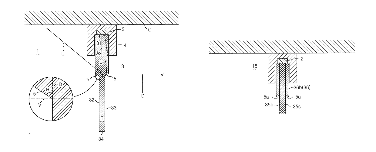
[0015]An illumination device will be described with reference to FIG. 1. The illumination device 1 includes a light source unit 2, a light guide plate 3 configured to guide light L (indicated by broken-line arrows) from the light source unit 2 and to emit the light L outward, and a case 4 configured to hold the light source unit 2 and the light guide plate 3. The case 4 is mounted to a ceiling C and is configured to hold the light guide plate 3 to be orthogonal to the ceiling C. For example, the light source unit 2 includes, as a light source, a white LED (not illustrated) which emits white light. The white LED is disposed so that the optical axis Ax thereof is oriented in a vertical direction.

[0016]The light guide plate 3 is made of a light-transmitting material such as a transparent acryl plate or the like. The light guide plate 3 includes an incidence surface 31 which constitutes one end surface of the light guide plate 3 and on which the light coming from the light source unit ...

seventh embodiment

[0026]Next, an illumination device will be described with reference to FIG. 6. An illumination device 19 is based on the illumination device 12 described above and is further provided with a reflection plate 9 which reflects the light L reflected by the stepped surfaces 5 toward the floor surface. The reflection plate 9 is made of a material having high light reflectivity, e.g., aluminum, and is held in a space between the light guide plate 3 and the case 4 so as to cover the stepped surfaces 5. The provision of the reflection plate 9 helps increase the amount of light directed toward the floor surface. Thus, the high brightness light emission on the end emission surface 34 of the light guide plate 3 becomes less conspicuous. It is therefore possible to obtain natural irradiation light.

[0027]The illumination device according to the disclosure is not limited to the aforementioned embodiments and the modifications thereof. For example, it is not always necessary to provide the steppe...


PUM


Abstract

An illumination device includes a light source unit and a light guide plate configured to guide light coming from the light source unit. The light guide plate includes an incidence surface, main emission surfaces from which the light incident on the incidence surface is emitted, and an end emission surface which is opposed to the incidence surface and from which the light is emitted. At least one of the main emission surfaces has a stepped surface which is formed such that the thickness of the light guide plate becomes thinner at a side of the end emission surface than at a side of the incidence surface. The stepped surface is configured to reflect the light in a direction opposite to a light guide direction extending from the incidence surface toward the end emission surface and inclined with respect to the light guide direction.

Description

CROSS-REFERENCE TO RELATED APPLICATIONS[0001]This application claims priority to Japanese Patent Application No. 2015-127431 filed on Jun. 25, 2015, the entire contents of which are incorporated herein by reference.TECHNICAL FIELD[0002]The disclosure relates to an illumination device provided with a light guide plate.BACKGROUND ART[0003]In the related art, there is known an illumination device provided with a light guide plate which guides the light emitted from a light source unit and which emits the light outward (see, e.g., Japanese Unexamined Patent Application Publication No. 2004-228018A). The light guide plate includes an incidence surface on which the light emitted from the light source unit is incident. The light guide plate emits the light incident on the incidence surface to the outside from both main surfaces while guiding the light toward an emission end surface opposed to the incidence surface.[0004]However, if the aforementioned illumination device is installed on a c...

Claims


Application Information

Patent Timeline
Patent Type & Authority Patents(United States)
IPC IPC(8): F21V8/00F21S8/04F21V7/00F21V7/22F21V13/02F21Y103/10F21Y115/10
CPCG02B6/0045F21S8/04F21V7/0058F21Y2115/10F21V13/02F21Y2103/10F21V7/22F21V7/24G02B6/002G02B6/0038G02B6/0055G02B6/0075G02B6/0091
Inventor KAWACHI, HIDEHARUANAMI, SHINICHITANAHASHI, OSAMUSEKII, HIROYUKI
Owner PANASONIC INTELLECTUAL PROPERTY MANAGEMENT CO LTD
Why Eureka
Try Eureka