
Plug for connection to a socket of a panel of an electronic equipment housing having anti-breakage means for the optical cable on which the plug is mounted

a technology of electronic equipment and sockets, which is applied in the direction of coupling device connections, instruments, optical elements, etc., can solve the problems of difficult manual access to the unlocking device of the optical contacts of the plug, insufficient heat dissipation of the optoelectronic converter, and increased difficulty in connecting the optical contacts and optoelectronic converters. to achieve the effect of simple traction for

Active Publication Date: 2018-07-10
RADIALL SA
View PDF13 Cites 4 Cited by
  • Summary
  • Abstract
  • Description
  • Claims
  • Application Information

AI Technical Summary

Benefits of technology

[0021]Thanks to the invention, an automatic disconnection between optical contact(s) lodged in the rear part and optoelectronic converter in the front part is easily assured, by a simple traction force exerted on the bushing, and without risk of breaking the optical conductor or conductors, such as optical fibers, of the optical cable on which the rear part of the plug body is mounted.
[0022]The floating mounting of the front part on the rear part of the plug body furthermore allows this front part to remain off axis in the socket cavity, even if the rear part of the body itself tends to realign itself with said cavity, especially during a locking of the plug on the socket.
[0023]A subsequent advantage due to the floating mounting between front part and rear part of the plug body is that any mechanical stresses applied to the rear part of the plug are not transmitted to the front part and thus to the electronic component mounted on the electronic equipment card. This is advantageous, since such a component is particularly vulnerable to the mechanical forces to which it is submitted by virtue of being held by soldering on the surface of the printed circuit of the card, which is not able to withstand major forces.
[0027]According to another advantageous embodiment, the bushing carries a seal adapted to produce tightness at the interface between the plug and the socket in which the front part of the plug body is designed to be seated. With such a seal, a perfect tightness is provided at the interface between plug and socket. Moreover, the locking force of the plug on the socket may be transmitted efficiently and uniformly to the seal so as to compress it. The seal is preferably carried by the front part and may be made of silicone, MDPE, or any other polymer meeting the requirements of tightness.
[0029]The invention thus prevents any traction on the optical fiber bearing the optical contact(s) which might result in their breaking. In fact, with the plugs according to the prior art if a user tries to dismantle the converter from the rest of the plug without having first loosened the packing gland, the optical fiber may break. With the plug according to the invention, in such a situation if the user pulls on the front part there occurs an automatic disconnection of the optical contacts of the optoelectronic converter, and thus an immediate relaxation of any traction stress harmful to the optical fiber.

Problems solved by technology

First of all, the dissipation of heat generated in the optoelectronic converter may not be satisfactory.
The connection between optical contacts and the optoelectronic converter might not be easy.
Furthermore, the integration of the optoelectronic converter in the socket makes manual access to the unlocking device of the optical contacts of the plug more difficult.
Moreover, with a socket having an integrated optoelectronic converter it may prove difficult to achieve a satisfactory alignment between the electrical interface of the plug and that of the socket, despite the tolerances provided by the manufacturers.
It may also prove difficult to adapt a socket with integrated optoelectronic converter to different optical interface standards such as those of optical interfaces using LC or SC contacts.
While this solution is satisfactory overall, the inventors have discovered that there still exists in such an optical plug a risk of breakage of the optical conductor(s).
In fact, without having taken the previous precaution of having physical access to the optical contacts connected to the optoelectronic converter, a user may exert an unwanted traction on the optical cable and / or on the converter in order to separate the latter from the plug body.

Method used


Image

  • Plug for connection to a socket of a panel of an electronic equipment housing having anti-breakage means for the optical cable on which the plug is mounted
  • Plug for connection to a socket of a panel of an electronic equipment housing having anti-breakage means for the optical cable on which the plug is mounted
  • Plug for connection to a socket of a panel of an electronic equipment housing having anti-breakage means for the optical cable on which the plug is mounted

Examples


Embodiment Construction

[0030]Other advantages and characteristics of the invention will emerge better upon perusal of the detailed description of exemplary embodiments of the invention provided as an illustration and without limitation, making reference to the following figures, among which:

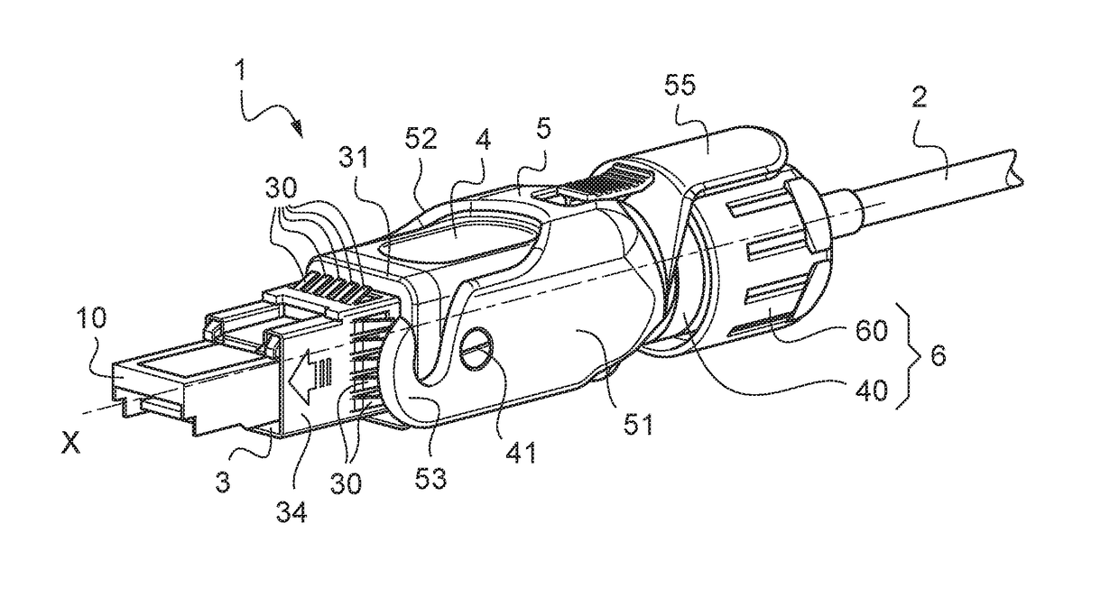
[0031]FIG. 1 is a perspective view of an optical plug according to the invention, the plug integrating an optoelectronic converter of “SFP transceiver” type, protruding toward the front of the plug;

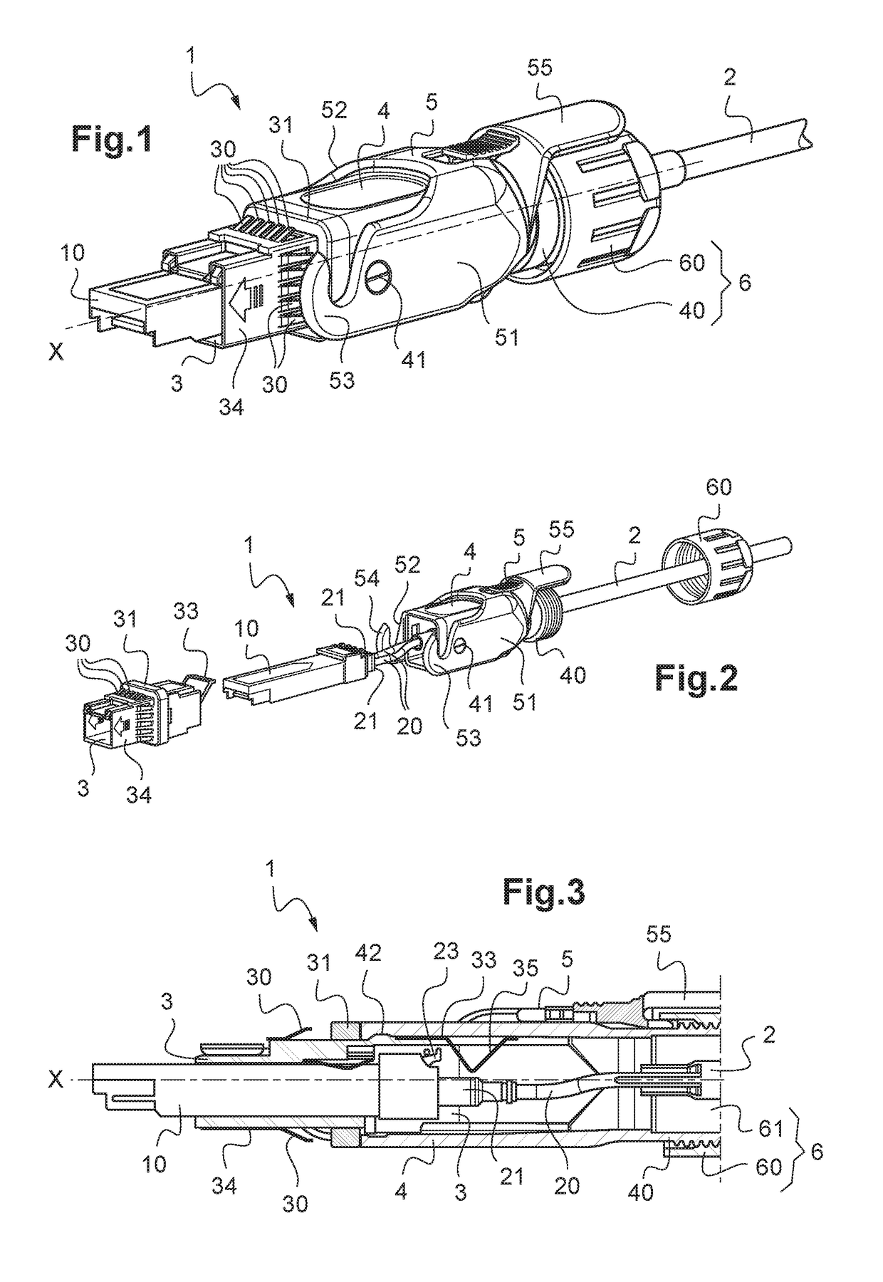
[0032]FIG. 2 is an exploded view of the plug according to FIG. 1;

[0033]FIG. 3 is a partial longitudinal section view of the plug according to FIGS. 1 and 2;

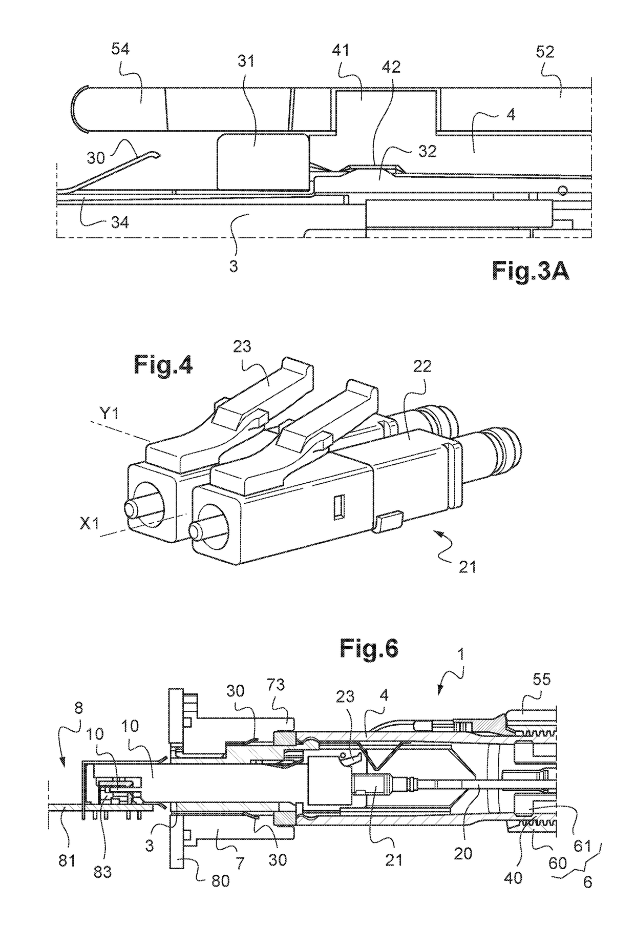
[0034]FIG. 3A is a detail top view of the plug according to one of FIGS. 1 to 3 showing the floating mounting of the front part of the plug body around its front part;

[0035]FIG. 4 is a perspective view of one example of optical contacts, of LC type, meant to be connected to an optoelectronic converter of the optical plug according to the invention;

[0036]FIGS. 5A to 5E sho...


PUM


Abstract

A plug mounted on an optical cable with one or more optical contacts each one having a tab which is deformable elastically or mounted so as to pivot relative to the rest of the contact, including: a body including a front part and a rear part; a bushing fitted around the front part with axial sliding forward, the bushing bearing a tab with an appendage extending inside the rear part, the tab of the bushing and the tab of each contact being disposed relative to each other so that when a traction force is applied to make the bushing slide around the front part, the appendage is able to bear against the tab of each contact so as to deform it elastically or make it pivot until the disconnection is produced between the contact and the converter.

Description

TECHNICAL FIELD[0001]The present invention concerns a plug designed to be mounted on an optical cable comprising at least one optical conductor having one or more contacts, and to be connected to a panel socket of an electronic equipment housing.[0002]The invention applies in particular to the plugs for connection to the socket of electronic equipment which implement several optical pathways with connections which are found outdoors and / or in harsh conditions particularly in telecommunications installations such as mobile telephone antenna relays, in high-speed data transmission networks for households or industry, in surveillance camera networks or for data transmission in railway installations.PRIOR ART[0003]It is known how to use optical pathway plugs having an optoelectronic converter of SFP or SFP+ type for example, also called transceivers. In the known plugs, the optoelectronic converter is usually borne by a socket attached to a panel of the electronic equipment housing, one...

Claims


Application Information

Patent Timeline
Patent Type & Authority Patents(United States)
IPC IPC(8): G02B6/36H01R13/52G02B6/38G02B6/42H01R13/53
CPCG02B6/4292G02B6/3893H01R13/53G02B6/4284H01R13/5219G02B6/4278
Inventor DUPEUX, BENOITBOURGEAS, FABIENLOMUSCIO, DOMINIQUE
Owner RADIALL SA
Learn More