Locomotive fixation rolling test rack traction indicator table

A rolling test bench and traction force technology, which is applied in the direction of measuring the traction/propulsion power of vehicles, can solve the problems of poor universality of special couplers, no anti-break protection structure, and limitation of coupler telescopic distance, so as to achieve flexible adjustment of coupler expansion and easy control. The effect of moving the locomotive and improving the life of the reducer

Active Publication Date: 2012-05-02
CRRC DALIAN INST CO LTD
View PDF7 Cites 9 Cited by
  • Summary
  • Abstract
  • Description
  • Claims
  • Application Information

AI Technical Summary

Problems solved by technology

[0008] 1) The axis of the screw and the axis of the coupler are not in the same axis, resulting in an overturning moment and poor safety
[0009] 2) The axial force of the screw will cause the reducer to bear part of the axial force, which is easy to damage the reducer
[0010] 3) The special coupler needs to be specially made, and the versatility is poor
[0011] 4) There is no anti-break protection structure, which has potential safety hazards
[0012] 5) Complex structure, high cost and poor reliability
[0016] 1) The retractable distance of the coupler is limited, and it is inconvenient to add a push-pull rod for long-distance adjustment
[0017] 2) There is still no anti-break protection structure, which has potential safety hazards
[0018] 3) The transmission bears part of the axial force, and the transmission is easily damaged
[0019] 4) The stability of the coupler is poor when it is under pressure, which is not convenient for the accurate positioning of the locomotive
[0020] 5) The special coupler has poor versatility

Method used


Image

  • Locomotive fixation rolling test rack traction indicator table
  • Locomotive fixation rolling test rack traction indicator table
  • Locomotive fixation rolling test rack traction indicator table

Examples


Embodiment Construction

[0043] The present invention is further described in conjunction with accompanying drawing:

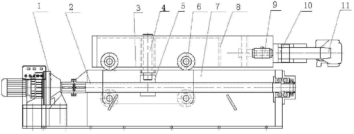
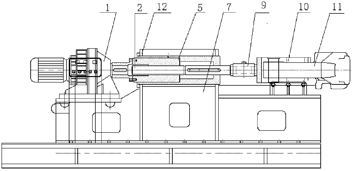
[0044] Existing traction gauges such as figure 1 As shown, the traction meter platform is divided into upper and lower parts, the upper part is composed of special coupler 11, traction rod 10, load cell 9, mobile frame 8, guide wheel 6, force transmission pin 4, etc.; the lower part is composed of reducer 1. Screw 2, nut 5, frame 7, etc.; the upper part is connected with the lower nut 5 through the force transmission pin 4, the screw 2 rotates to drive the nut 5 to move linearly, and the upper and lower parts are connected through the force transmission pin 4, The guide wheel 6 moves horizontally along the guide plate 3 and transmits horizontal force. Speed ​​reducer 1 drives screw rod 2 to rotate, and nut 5 reciprocates in a straight line, and force transmission pin 4 on nut 5 drives mobile frame 8, load cell 9, traction rod 10, special coupler 11 to telescopically move, and the pus...


PUM


Abstract

The invention discloses a locomotive fixation rolling test rack traction indicator table; a speed reducer shaft is parallel to a screw rod which is screwed with a nut; a chain wheel arranged on the speed reducer shaft is connected with a chain wheel arranged on the nut by a chain; one end of the screw rod is connected with a traction dynamometry device; the traction dynamometry device comprises aguide frame, a force sensor, a traction connecting rod and a draw gear which are sequentially connected from inside to outside; and a safety pull rod and a safety switch are also arranged between theguide frame and the traction connecting rod. The device is compact in structure and long in stretching movement distance of the draw gear, and is capable of being basically compatible with the requirements of center distances of draw gears of various types of locomotives at present. The locomotive fixation rolling test rack traction indicator table is reasonably applied with force so as to reducethe upsetting moment and improve the safety. The No. 13 draw gear which meets the national standard is adopted, so that the problems of universality and convenience can be solved. An anti-breakage structure and the safety pull rod are adopted, so that secondary mechanical protection can be formed, and the safety is high. The locomotive fixation rolling test rack traction indicator table is capable of bearing the traction of the draw gear of the locomotive and providing tension and pressure to the locomotive so as to conveniently control the movement of the locomotive and accurately locate as well as be high in efficiency and applicable to a running test of the locomotive.

Description

technical field [0001] The invention relates to a traction force meter of a fixed rolling test bench for a locomotive, which belongs to the technical field of locomotive test equipment. Background technique [0002] Before the locomotive is delivered for use, it must be tested on the line. The locomotive runs on the fixed rolling test bench, which can basically replace the locomotive for the test on the line. The indoor test can improve the production efficiency of the production plant and the operation department. The locomotive enters the test bench through the guide beam device, and is centered up and down with the pre-placed rail wheels in the foundation pit of the test bench. For running on an infinitely long track, the measurement of the traction force of the locomotive coupler is provided by a traction meter. [0003] There is a standard coupler at both ends of each locomotive. When setting the rolling table test on each locomotive, the locomotive first takes the tra...

Claims


Application Information

Patent Timeline
Patent Type & Authority Applications(China)
IPC IPC(8): G01L5/13
Inventor 刘和才王磊吴昕
Owner CRRC DALIAN INST CO LTD
Why Eureka
Try Eureka