Joint bearing flanging tool and process of using same for joint bearing flanging

A joint bearing and tool technology, which is applied in the field of aircraft engines, can solve the problems that the processing is difficult to meet the requirements and the flanging tools cannot be designed, and achieves the effect of uniform force, favorable for rotary extrusion and less equipment.

Active Publication Date: 2017-04-26
CHENGDU ENGINE GROUP
View PDF9 Cites 7 Cited by
  • Summary
  • Abstract
  • Description
  • Claims
  • Application Information

AI Technical Summary

Problems solved by technology

[0004] 1. Ensure that the flanging length of the joint bearing is ≥0.254mm; while the tolerance of the groove center distance is ±0.076mm, the conventional flanging tools cannot be designed, and it is difficult to meet the requirements in processing;

Method used


Image

  • Joint bearing flanging tool and process of using same for joint bearing flanging
  • Joint bearing flanging tool and process of using same for joint bearing flanging
  • Joint bearing flanging tool and process of using same for joint bearing flanging

Examples


Embodiment

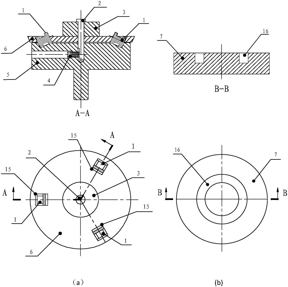
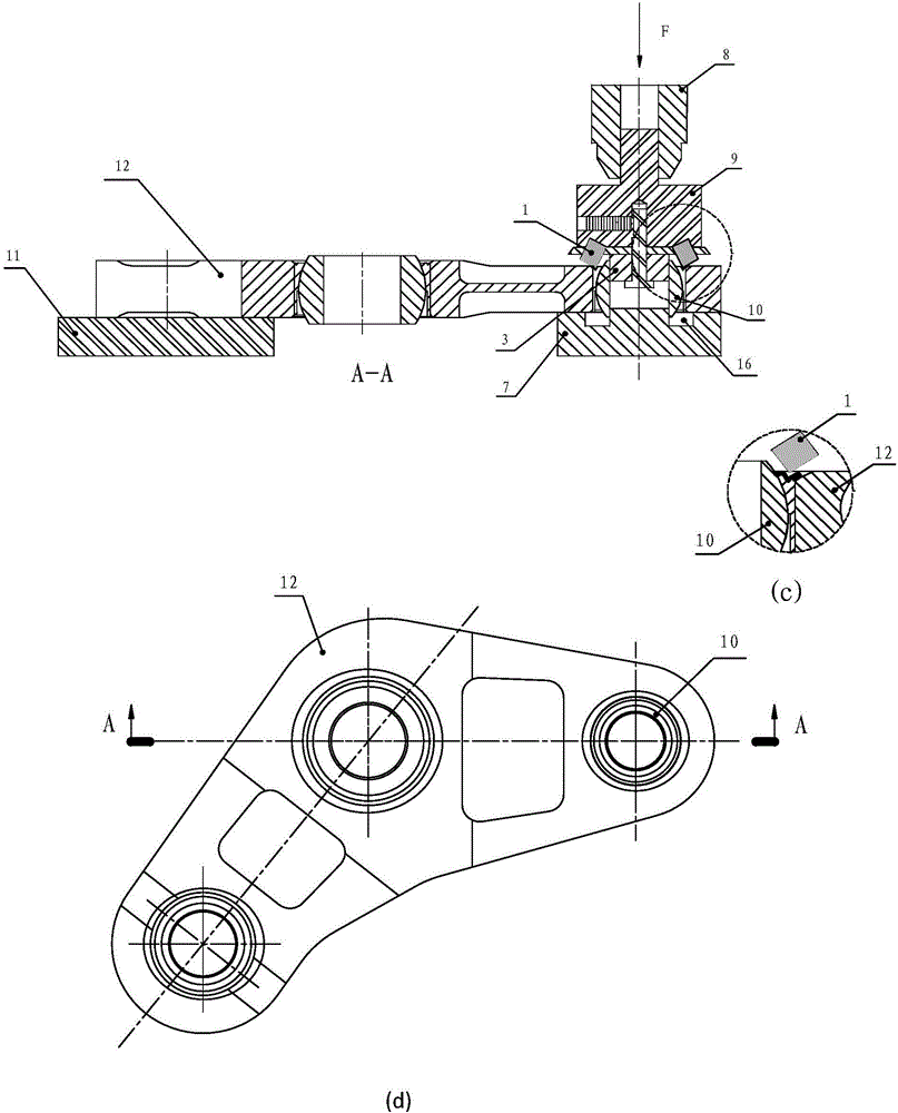
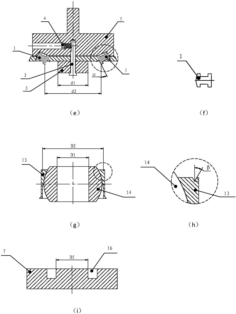
[0048] In this embodiment, the diameter of the flanged spherical plain bearing 10 is 76.193, and the diameter dimension D2 of the lowest point of the groove of the spherical plain bearing bush 13 is 73.076±0.076 in diameter, and the inclination angle β of the groove of the spherical plain bearing bush 13 is 30°. The joint bearing ball 14 is a joint bearing in which the diameter D1 of the inner hole is 48±0.02. The size of the joint bearing flanging tool 9 used is to ensure that after the bearing flanging tool 9 is assembled, the diameter d2 of the sharp point of the roller 1 after assembly is 73.076±0.076, the inclination angle α of the roller 1 after assembly is 30°, and its positioning support seat The inner diameter D5 of the annular positioning groove of 7 is 48, and the diameter d1 of the guide pin 3 is 48; after assembly, the assembly gap between the end face of the bearing support 5 and the end face of the cage 6 is 0.02-0.05 mm; the parameter specification requirements:...


PUM


Abstract

The invention relates to a joint bearing flanging tool for aviation hanging parts, and a process of using the same for joint bearing flanging. The joint bearing flanging tool mainly comprises a roll, a retainer, a guide pin, a force-bearing support seat and a location support seat, wherein clearance fit is formed among the components; and the bearing flanging tool needs to be used in a manner of being matched with the flanged joint bearings in the hanging parts in specification and dimension during use. The joint bearing flanging tool is simple in structure, uniform in stress, capable of being automatically centred, stable in performance, reliable in quality, and capable of ensuring stability and smoothness during joint bearing flanging. According to the process of using the joint bearing flanging tool for bearing flanging, which is disclosed by the invention, the joint bearing flanging tool is installed on a spindle of a radial drilling machine, each flanged bearing is rotated and extruded to the required flanging dimensions through enabling the roll to contact with the groove surface of the flanged bearing. The process is stable in machining, simple to operate, short in alignment time, high in efficiency, stable in quality, and convenient for batch production.

Description

technical field [0001] The invention belongs to the technical field of aircraft engines, and in particular relates to a joint bearing flanging tool for aviation suspension parts and a new technology for the joint bearing flanging thereof. Background technique [0002] Since the aviation suspension parts equipped with joint bearing balls are special-shaped parts, their weight is heavy; and it is required that the surface of the processed suspension parts is not allowed to be scratched after being shot blasted as a whole. At present, for the flanging of joint bearings in aviation suspension parts, traditional processing technology and existing flanging tools are used, that is, the special extrusion ball cutter for lathes is used as a flanging tool to realize the flanging of joint bearings on a lathe. However, using the existing bearing flanging tool and the flanging process realized on the lathe cannot meet the technical requirements in actual use. And it can only process joi...

Claims


Application Information

Patent Timeline
Patent Type & Authority Applications(China)
IPC IPC(8): B21D53/10B21D39/00
CPCB21D39/00B21D53/10
Inventor 钟旭牟玉芬杨霄胡开菊
Owner CHENGDU ENGINE GROUP
Why Eureka
Try Eureka