Packaging for containers

a container and packaging technology, applied in the field of packaging for containers, can solve the problems of increasing and contaminating or breaking containers, and achieve the effect of reducing the amount of packaging materials used and facilitating the opening

Active Publication Date: 2018-07-17
BECTON DICKINSON FRANCE
View PDF14 Cites 4 Cited by
  • Summary
  • Abstract
  • Description
  • Claims
  • Application Information

AI Technical Summary

Benefits of technology

[0016]Another goal of the invention is to provide a global packaging which reduces the amount of packaging mat

Problems solved by technology

The applicant has found that the contamination or the breakage of the containers occurs, when packagings of the prior art are stacked, due, in part, to an insufficient distribution of the load of the upper packaging(s) on the lower packaging.
This insufficient distribution of the load le

Method used


Image

  • Packaging for containers
  • Packaging for containers
  • Packaging for containers

Examples


Embodiment Construction

[0056]Each container 2 comprises a cylindrical body, in particular tubular, and an upper surface that can be a flange located at or near the proximal end of this cylindrical body.

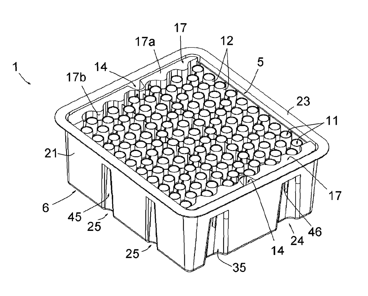
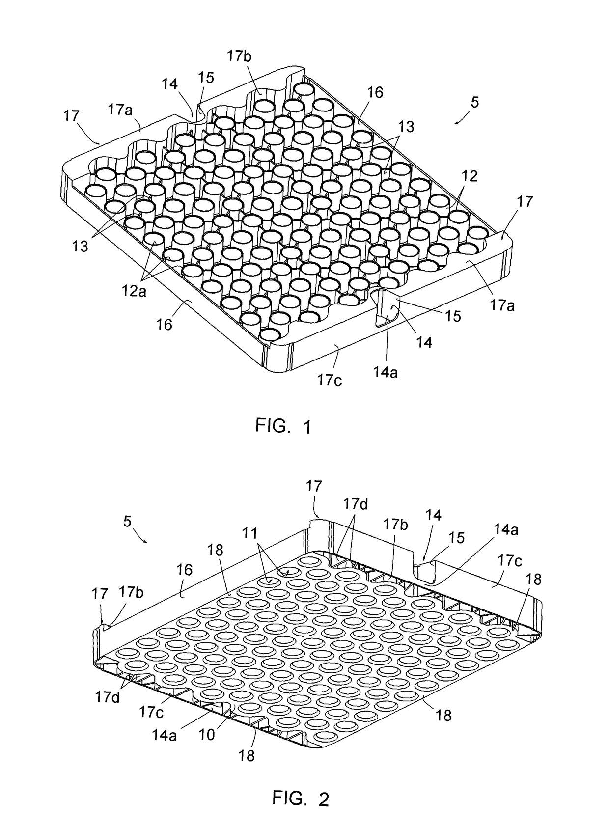
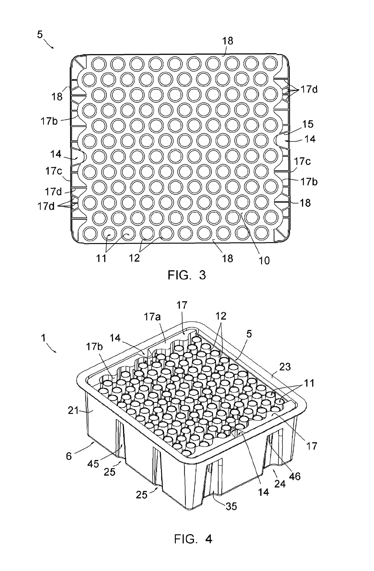
[0057]Referring more particularly to FIGS. 1-3, the nest 5 comprises a flat, substantially square or rectangular bottom wall 10, through openings 11 coaxially surrounded by chimneys 12, radial connection walls 13, notches 14 on first and second opposed edges of the bottom wall 10, walls 15 delimiting the notches 14, side walls 16 extending on third and fourth opposed edges of the bottom wall 10 that are perpendicular to said first and second edges, and two supporting elements 17 extending along said first and second opposed edges, along the portion of the nest comprising the chimneys. The nest 5 is formed by a single part of moulded plastic material.

[0058]The inferior edges of the supporting elements 17 and the edges of the bottom wall 10 form first supporting surfaces 18, intended to be received on corresp...


PUM


Abstract

This packaging is for containers having each a cylindrical body and an upper surface located at or near an extremity of the body, said packaging comprising a nest, a tub and a sealing cover; the nest having a nesting structure to receive the containers and comprising at least one first supporting surface, to be received on at least one corresponding supporting surface of the tub, the tub having a bottom wall, lateral walls forming an upper opening, and a peripheral flange leveled with said upper opening, for the sealing of said sealing cover thereon; said nest includes at least one second supporting surface rigidly connected to said at least one first supporting surface and so positioned with respect to this at least one first supporting surface that this second supporting surface is located, when the nest is placed in the tub, at the level of said peripheral flange.

Description

BACKGROUND OF THE INVENTION[0001]Field of the Invention[0002]This invention is directed to a packaging for containers such as, for example, syringes or cartridges. Each container notably comprises a cylindrical body, in particular tubular, and “upper surface” located at or near the proximal end of this cylindrical body. This upper surface is generally formed by a flange that can be integrally formed with the cylindrical body or that can be a separate piece mounted on this body.[0003]In this application, the distal end of a component or of a device means the end furthest away from the hand of the user and the proximal end means the end closest to the hand of the user, when the component or device is in the use position. Similarly, in this application, the terms “in the distal direction” and “distally” mean in the direction of the injection, and the terms “in the proximal direction” and “proximally” mean in the direction opposite to the direction of injection.[0004]Discription of Rela...

Claims


Application Information

Patent Timeline
IPC IPC(8): B65D21/00B65D21/04A61M5/00
CPCB65D21/04A61M5/008B65D21/045A61M5/00B65D21/02B65D85/42
Inventor CARREL, FRANCK
Owner BECTON DICKINSON FRANCE
Why Eureka
Try Eureka