Cryopump and vacuum pumping method
a vacuum pumping and cryopump technology, applied in the direction of pumps, machines/engines, pumps, etc., can solve the problem that the cryopump cannot play an actual role sufficiently, and achieve the effect of increasing the amount of gas condensed
- Summary
- Abstract
- Description
- Claims
- Application Information
AI Technical Summary
Benefits of technology
Problems solved by technology
Method used
Image
Examples
first embodiment
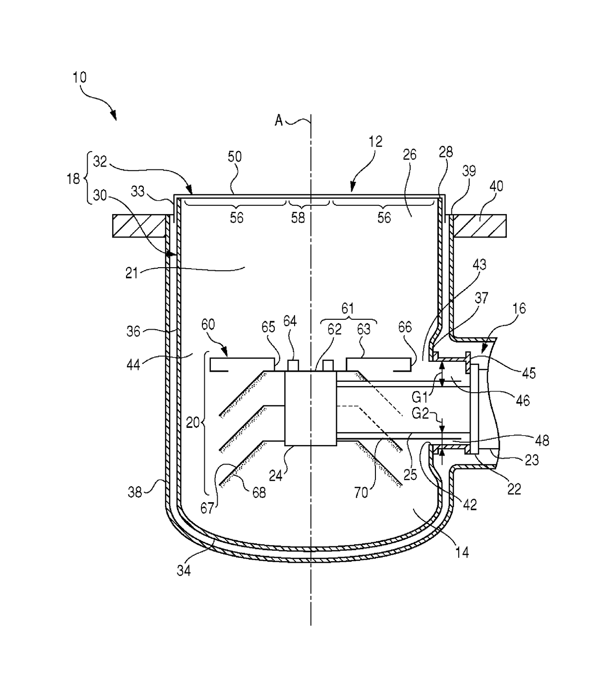
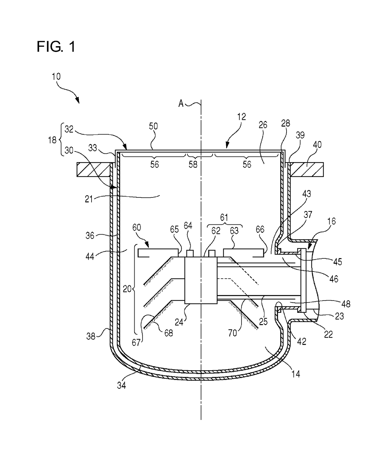
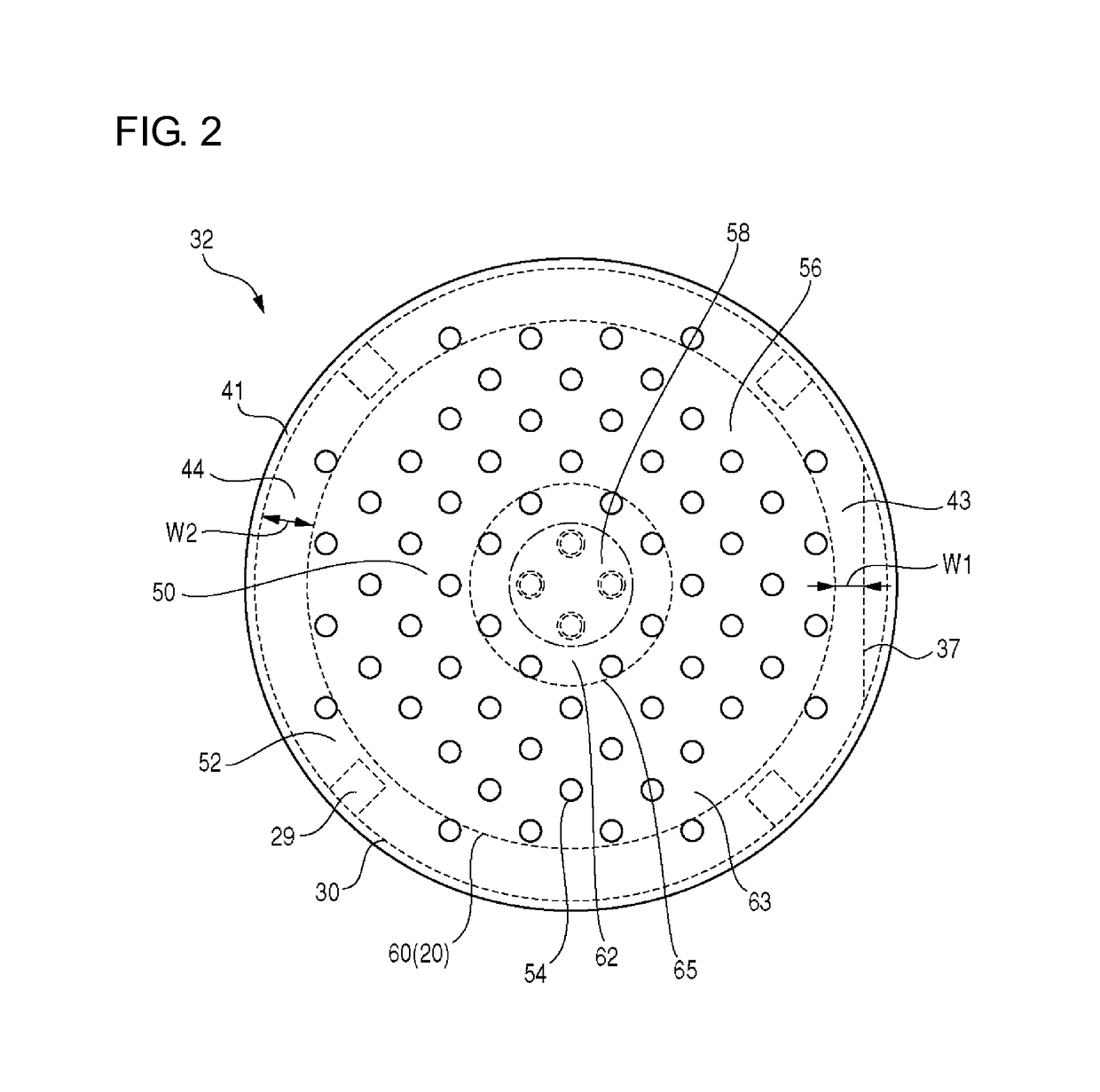
[0019]FIG. 1 is a schematic sectional side view of a main part of a cryopump 10 according to the present invention. The cryopump 10 is mounted on a vacuum chamber of, for example, an ion implantation apparatus or a sputtering apparatus and used to increase the degree of vacuum inside the vacuum chamber to a level demanded by a desired process. The cryopump 10 includes an inlet 12 to receive gases. Gases to be pumped flow from the vacuum chamber on which the cryopump 10 is mounted, through the inlet 12, into an internal space 14 of the cryopump 10. FIG. 1 is a cross-sectional view including a central axis A of the internal space 14 of the cryopump 10.
[0020]Note that terms “axial direction” and “radial direction” may be used herein to facilitate an understanding of a positional relationship among components of the cryopump 10. The axial direction represents a direction through the inlet 12 (a direction along the dashed-dotted line A in FIG. 1), and the radial direction represents a di...
third embodiment
[0074]As illustrated in FIG. 6, arrangement of the second cryopanel 20 is adjusted so that the width of the lateral gap 43 and the width of the opened annular gap 44 may correspond to each other. As illustrated by the arrow F, the second cryopanel 20 is located to be away from the attaching pedestal 37 such that a center of the second cryopanel 20 is deviated from the central axis A. The second cryopanel 20 is off-centered from the central axis A so as to be away from a higher-temperature side of the refrigerator 16. In this manner, the narrowed part of the lateral gap 43 is widened, and on the opposite side across the central axis A, the opened annular gap 44 is narrowed. In a similar manner to that in the third embodiment, the width of the gap surrounding the side surface of the condensing layer growing on the top panel 60 can be uniformed.
[0075]FIG. 7 is a schematic sectional side view of a main part of the cryopump 10 according to a fifth embodiment of the present invention. In ...
embodiment 1
[0094]2. The cryopump , wherein
[0095]the second cryopanel comprises a front face opposed to the plate main portion, the front face comprising a central region and an outside region surrounding the central region, and wherein
[0096]the gas passing region is opposed to the outside region while the gas shielding region is opposed to the central region.
[0097]3. The cryopump according to embodiment 1 or embodiment 2, wherein
[0098]the radiation shield comprises a side portion enclosing the second cryopanel, and between the side portion and the second cryopanel is formed a gap having a narrowed part, and wherein
[0099]the gas shielding region is formed at a position corresponding to the narrowed part.
[0100]4. The cryopump according to any one of embodiments 1 to 3, wherein
[0101]the radiation shield comprises an attaching pedestal located lateral to the second cryopanel for attachment of the refrigerator to the radiation shield, and an annular part adjacent to the attaching pedestal and enclo...
PUM
 Abstract
Description
Claims
Application Information
 - R&D Engineer
- R&D Manager
- IP Professional
- Industry Leading Data Capabilities
- Powerful AI technology
- Patent DNA Extraction
Browse by: Latest US Patents, China's latest patents, Technical Efficacy Thesaurus, Application Domain, Technology Topic, Popular Technical Reports.
© 2024 PatSnap. All rights reserved.Legal|Privacy policy|Modern Slavery Act Transparency Statement|Sitemap|About US| Contact US: help@patsnap.com


