
Tissue visualization and modification device

a technology which is applied in the field of tissue visualization and modification device, can solve the problems of reducing the blood flow through a blood vessel, adversely affecting the functioning and/or health of that organ, and compromising the function of one or more nerves

Active Publication Date: 2018-08-14
TRICE MEDICAL
View PDF388 Cites 29 Cited by
  • Summary
  • Abstract
  • Description
  • Claims
  • Application Information

AI Technical Summary

Benefits of technology

The patent is for a system for imaging the body through a minimally invasive device. The system includes an access device and an elongated member that can be moved through the access device. The system also includes visualization elements and illumination elements positioned at the end of the device. The invention provides methods and kits for using the system for imaging applications. The benefits of the invention are improved accuracy and efficiency in imaging the body, with reduced risk of complications and discomfort for the patient.

Problems solved by technology

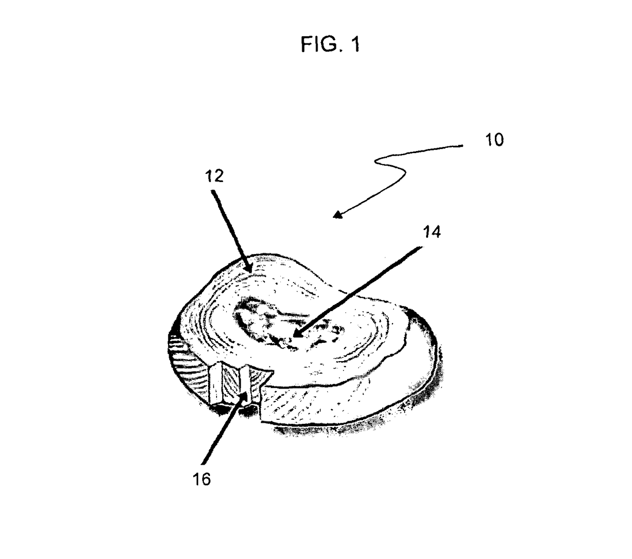
For example, a cancerous tumor may press against an adjacent organ and adversely affect the functioning and / or the health of that organ.
In other cases, bony growths (or “bone spurs”), arthritic changes in bone and / or soft tissue, redundant soft tissue, or other hypertrophic bone or soft tissue conditions may impinge on nearby nerve and / or vascular tissues and compromise functioning of one or more nerves, reduce blood flow through a blood vessel, or both.
The proteoglycan and water from within the nucleus decreases which in turn results in the nucleus drying out and becoming smaller and compressed.
Additionally, the annulus tends to thicken, desiccate, and become more rigid, lessening its ability to elastically deform under load and making it susceptible to disc fissures.
Additionally, biochemicals contained within the nucleus pulposus may escape through the annulus causing inflammation and irritating adjacent nerves.

Method used


Image

  • Tissue visualization and modification device
  • Tissue visualization and modification device
  • Tissue visualization and modification device

Examples


Embodiment Construction

[0017]Aspects of the invention include minimally invasive imaging system. Systems according to embodiments of the invention include: an access device having a proximal end and distal end and an internal passageway extending from the proximal to distal end; and an elongated member dimensioned to be slidably moved through the internal passageway of the access device and having a proximal end and a distal end. In the systems of the invention, at least one of multiple visualization elements and multiple illumination elements are positioned among the distal ends of the access device and the elongated member. Also provided are methods of using the systems in imaging applications, as well as kits for performing the methods.

[0018]Before the present invention is described in greater detail, it is to be understood that this invention is not limited to particular embodiments described, as such may, of course, vary. It is also to be understood that the terminology used herein is for the purpose...


PUM


Abstract

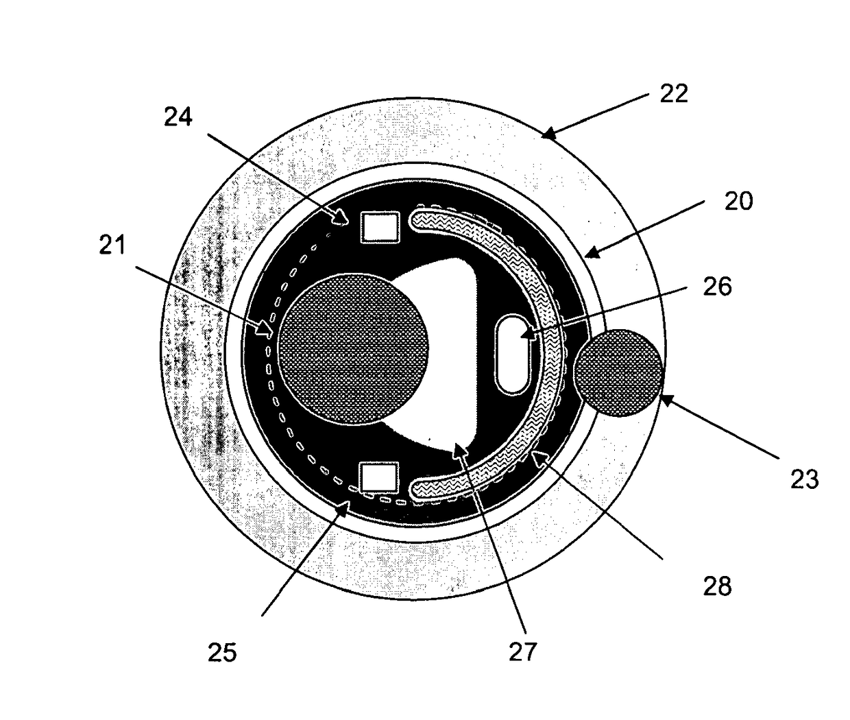
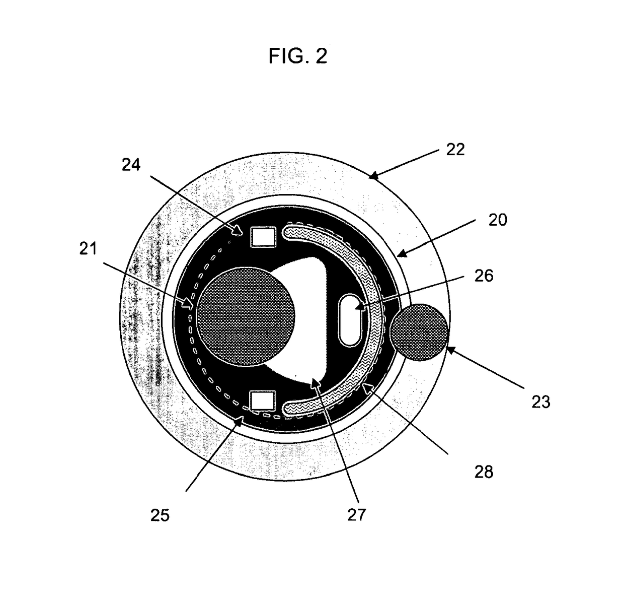
A tissue visualization and modification device may include a rigid access body having a longitudinal axis, an internal passageway extending from the proximal end to the distal end, and an access body imaging sensor positioned on the distal end of the body and protruding inward beyond an inner wall into the internal passageway. An elongated member may be slidably positioned within the rigid access body. The elongated member may include, when viewed substantially along the longitudinal axis, a dissection electrode in the shape of a semicircle, an irrigation channel positioned within the semicircle, an aspiration channel positioned partially within the semicircle and adjacent the irrigation channel, first and second illumination elements positioned adjacent the respective tips of the semicircle and an elongated member imaging sensor positioned adjacent the aspiration channel.

Description

CROSS-REFERENCE TO RELATED APPLICATIONS[0001]This application is continuation of U.S. patent application Ser. No. 12 / 269,770, filed Nov. 12, 2008, the entirety of which is hereby incorporated by reference herein.BACKGROUND OF THE INVENTION[0002]Many pathological conditions in the human body may be caused by enlargement, movement, displacement and / or a variety of other changes of bodily tissue, causing the tissue to press against (or “impinge on”) one or more otherwise normal tissues or organs. For example, a cancerous tumor may press against an adjacent organ and adversely affect the functioning and / or the health of that organ. In other cases, bony growths (or “bone spurs”), arthritic changes in bone and / or soft tissue, redundant soft tissue, or other hypertrophic bone or soft tissue conditions may impinge on nearby nerve and / or vascular tissues and compromise functioning of one or more nerves, reduce blood flow through a blood vessel, or both. Other examples of tissues which may gr...

Claims


Application Information

Patent Timeline
Patent Type & Authority Patents(United States)
IPC IPC(8): A61B1/018A61B1/04A61B1/015A61B1/06A61B5/00A61B1/012A61B1/00A61B18/00A61B17/00
CPCA61B1/042A61B1/00087A61B1/00154A61B1/00181A61B1/0125A61B5/0084A61B2018/00982A61B1/00094A61B1/00193A61B1/015A61B2017/00296
Inventor OUYANG, XIAOLONGCYBULSKI, JAMES S.SEDDIQUI, FRED R.
Owner TRICE MEDICAL
Learn More