Perspective altering display system

a display system and perspective technology, applied in the field of display systems, can solve the problems of oppressive use of 3-d glasses or other paraphernalia, existing video display systems are restricted either in their utility or in their realism, and the size of flat panel displays is growing and falling, so as to increase reduce the resolution of the scene

Active Publication Date: 2018-08-28
VIDEA
View PDF39 Cites 8 Cited by
  • Summary
  • Abstract
  • Description
  • Claims
  • Application Information

AI Technical Summary

Benefits of technology

[0010]The sensor may be operative to detect the viewer's distance from the display screen, with the processor being operative to increase the resolution of the scene as the viewer moves closer to the display screen and decrease the resolution of the scene as the viewer moves away from the display screen. A camera with a tilt capability may be used for recording the scene, with the processor being further operative to tilt the camera in response to the viewer's up / down movement. The camera may have a field of view which includes a viewer of the display screen, enabling the display to function a virtual mirror.

Problems solved by technology

Flat panel displays are growing in size and falling in price.
However, existing systems for video display are restricted either in their utility or in their realism, due to the inherent limitations in a two-dimensional presentation unit.
The use of 3-D glasses or other paraphernalia is oppressive in those circumstances where a casual effect is desired, or where no user intervention is to be required.
Thus, prior-art systems relying on still or even video images, or various photographic or video projection techniques, cannot achieve the level of perception of reality that is desired for many residential or commercial display applications.

Method used


Image

  • Perspective altering display system
  • Perspective altering display system
  • Perspective altering display system

Examples


Embodiment Construction

[0033]This invention employs a variety of techniques to provide a unique experience for the viewer of a display, particularly large wall-mounted panels. In the preferred embodiments, the perception of a displayed image is altered for viewers moving relative to the position of the display system screen, thereby imparting a sense of three-dimensional immersion in the scene being displayed.

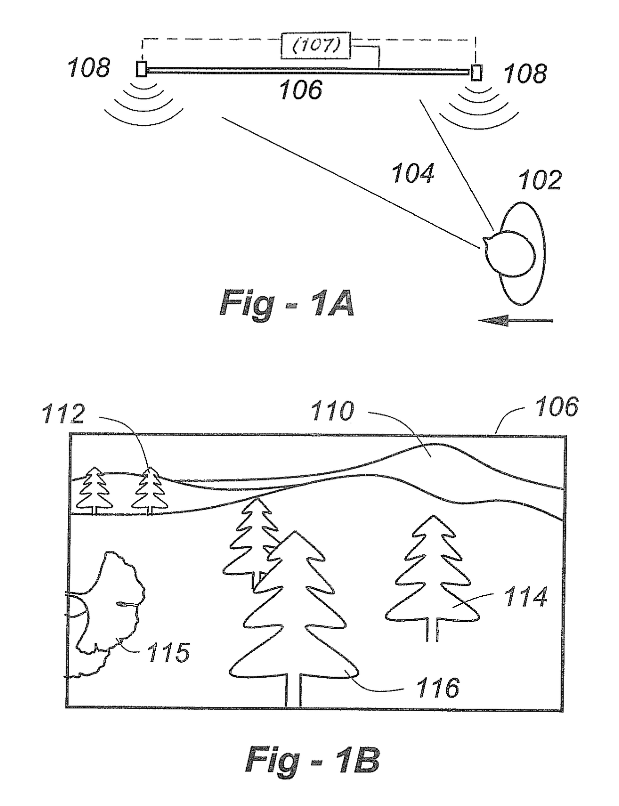
[0034]FIG. 1A shows a viewer 102 having a field of view 104 walking from the right towards the left relative to a display screen 106 driven by display generator 107. One or more sensors 108, which may use visible-light, infrared, ultrasonic, or other modalities described in further detail below, are used to track at least the lateral position of individual 102.

[0035]FIG. 1B is a simplified representation of what the person 102 might see on the display screen 106 according to the invention from the position shown in FIG. 1A. Relatively close objects are shown at 115, 116. Less close objects are seen a...


PUM


Abstract

The perception of a displayed image is altered for viewers moving relative to the position of the display system screen, thereby imparting a sense of three-dimensional immersion in the scene being displayed. A display generator generates a scene having foreground and background elements, and a display screen displaying the scene. A sensor detects the position of a viewer relative to the display screen, and a processor is operative to shift the relative position of the foreground and background elements in the displayed scene as a function of viewer position, such that the viewer's perspective of the scene changes as the viewer moves relative to the display screen. The foreground and background elements may be presented in the form of multiple superimposed graphics planes, and / or a camera may be used to record the scene through panning at sequential angles. The system may be used to implement virtual windows, virtual mirrors and other effects without requiring viewers or users to modify behavior or wear glasses, beacons, etc.

Description

REFERENCE TO RELATED APPLICATION[0001]This application claims priority from U.S. Provisional Patent Application Ser. No. 60 / 957,845, filed Aug. 24, 2007, the entire content of which is incorporated herein by reference.FIELD OF THE INVENTION[0002]This invention relates generally to display systems and, more particularly, to systems that alter perspective, synthesize depth perception and provide other capabilities, thereby enhancing the viewing experience.BACKGROUND OF THE INVENTION[0003]Flat panel displays are growing in size and falling in price. At this time, non-projection, true HD (i.e.—1080 p) 50″ displays are available in the $1,000 to $2,000 price range, and new models are introduced on a regular basis. When edge-lit liquid-crystal display (LCD) panels are replaced with back-lit white light-emitting diodes, another leap in technology will occur. When organic LED panels become viable, flexible, affordable wall-sized displays, including wrap-around configurations, should be poss...

Claims


Application Information

Patent Timeline
Patent Type & Authority Patents(United States)
IPC IPC(8): H04N21/442G09G5/00H04N21/422H04N21/4223H04N21/431H04N5/44
CPCH04N21/4223H04N21/42202H04N21/431H04N21/44218H04N13/368H04N13/373H04N13/366H04N13/279G09G2340/10G09G2340/12H04N2005/4428H04N2213/006G09G2340/125H04N21/42222H04N13/275
Inventor POSA, JOHN G.SCHWAB, BARRY H.
Owner VIDEA
Why Eureka
Try Eureka