Cascade-form wavelength division multiplexing optoelectronic transceiver device, system and method

a transceiver and cascade-form technology, applied in multiplex communication, instruments, optical elements, etc., can solve the problems of lack of upgradability, cost overhead, and drawbacks of wm, so as to eliminate wm wavelength multiplexing/demultiplexing boxes, cost overhead, and lack of upgradability

Active Publication Date: 2018-09-04
ORANGE SA (FR)
View PDF9 Cites 0 Cited by
  • Summary
  • Abstract
  • Description
  • Claims
  • Application Information

AI Technical Summary

Benefits of technology

[0014]The optoelectronic emitter-receiver device according to the invention makes it possible in a clever manner to eliminate the WM wavelength multiplexing / demultiplexing box. Indeed, it suffices that the TWDM or WDM OLT ports of the mixed optical distribution infrastructure each be equipped with a device according to the invention, and that the set of devices be connected directly to the CEx box of the mixed infrastructure. Consequently, there is no longer any need for the WM box between the OLT ports and the CEx, and the drawbacks of the WM namely among others its cost overhead and its lack of upgradability disappear.
[0030]Such a system is advantageous since it makes it possible to eliminate the WM boxes and all their interfaces with the TWDM and WDM OLT ports. It suffices to connect any of the optoelectronic emitter-receiver devices of the OLT ports to the CEx box, and then to connect the other devices to it in cascade, in any order. This system therefore furthermore exhibits great flexibility in respect of the planning and upgrading of the optical distribution infrastructure, as well as great ease of installation of the OLT ports.

Problems solved by technology

Consequently, there is no longer any need for the WM box between the OLT ports and the CEx, and the drawbacks of the WM namely among others its cost overhead and its lack of upgradability disappear.

Method used


Image

  • Cascade-form wavelength division multiplexing optoelectronic transceiver device, system and method
  • Cascade-form wavelength division multiplexing optoelectronic transceiver device, system and method
  • Cascade-form wavelength division multiplexing optoelectronic transceiver device, system and method

Examples


Embodiment Construction

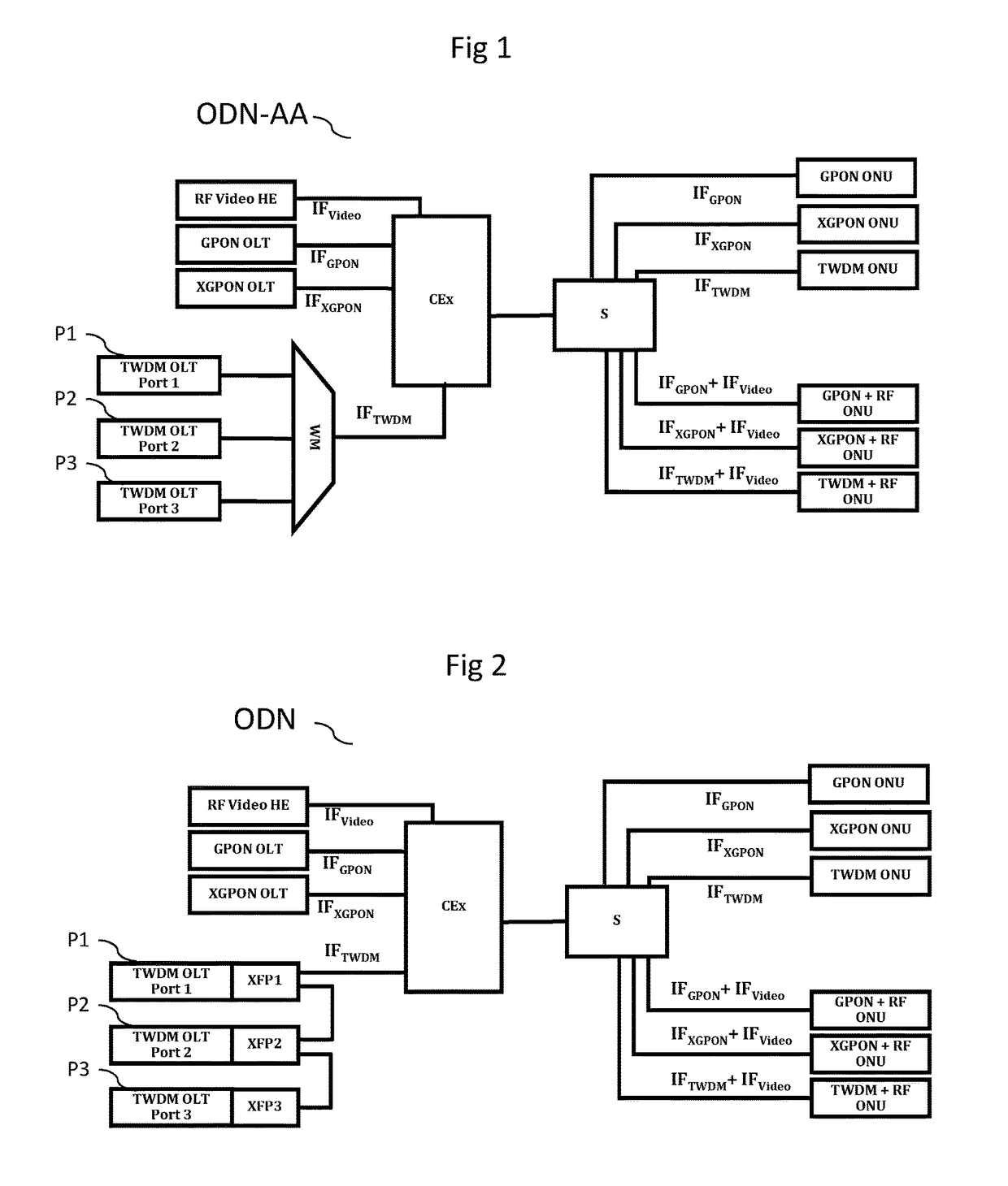
[0045]In the subsequent description, embodiments of the invention are presented in the case of mixed optical distribution infrastructures using WDM and / or TWDM techniques, in addition to TDM techniques. These infrastructures can comprise passive optical networks (PON) currently undergoing or shortly to undergo standardization at the ITU-T, such as the PON networks of NG-PON2 type, as well as other types of networks, in addition to or in place of PON networks, such as for example point-to-point optical networks.

[0046]FIG. 1 presents an ODN-AA mixed optical distribution infrastructure, according to the prior art.

[0047]For simplicity of illustration, this and the following figure show only a few TDM OLTs and only a few TWDM or WDM OLT ports, knowing that they may reach several tens or indeed several hundred in number in one and the same mixed optical distribution infrastructure. Likewise, only one ONU per OLT or per OLT port is illustrated, knowing that each OLT typically serves 64 or ...


PUM


Abstract

The invention relates to an optoelectronic transceiver device comprising a first optical connector (OC1) capable of connection to a first bidirectional optical fiber (OF1), and a second optical connector (OC2) capable of connection to a second bidirectional optical fiber (OF2), the device further comprising: an insertion-extraction module (ADM) capable of: extracting a wavelength (λRx) from a plurality of wavelengths constituting a first optical signal received by the first optical connector (OC1) and transmitting the first optical signal without the extracted wavelength to the second optical connector (OC2); inserting a wavelength (λTx) into a second optical signal received by the second optical connector (OC2) and transmitting the second optical signal with the inserted wavelength to the first optical connector (OC1); an electric-optical conversion module (EC1) capable of providing the insertion-extraction module with the wavelength (λTx) inserted into the second optical signal from an incoming electric signal (Data Tx); and an optical-electric conversion module (EC2) capable of converting the wavelength (λRx) extracted from the first optical signal by the insertion-extraction module into an outgoing electric signal (Data Rx).

Description

1. FIELD OF THE INVENTION[0001]The application for invention lies in the field of optical distribution networks (ODN) which serve subscribers to electronic communications services, and more particularly those which combine various types of wavelength multiplexing.2. PRIOR ART[0002]The architectures of optical access networks typically use a different wavelength per direction of transmission, the various users of a network sharing time windows of the signal. This technique called TDM (Time Division Multiplexing) shows limits in terms of maximum bitrates.[0003]Another technique allowing higher transmission bitrates, studied within standardization bodies by the SG15 group of the ITU (International Telecommunication Union), consists in associating a multiplex of wavelengths with users. This technique called WDM (Wavelength Division Multiplexing) is used alone by allocating a pair of wavelengths (upgoing and downgoing direction) per user, or in combination with the TDM technique, then du...

Claims


Application Information

Patent Timeline
Patent Type & Authority Patents(United States)
IPC IPC(8): H04J14/02G02B6/38G02B6/42H04B10/25H04Q11/00
CPCH04Q11/0071G02B6/3897G02B6/4246H04B10/2503H04J14/0212H04J14/0282H04Q11/0067H04J14/0223H04Q2011/0081H04Q2011/0016H04Q2011/0033H04J14/0201H04J14/0216H04J14/0278H04B10/2589
Inventor CHANCLOU, PHILIPPE
Owner ORANGE SA (FR)
Why Eureka
Try Eureka