Light guide device and virtual-image display device

a technology of virtual image and guide device, which is applied in the direction of instruments, polarising elements, optics, etc., can solve the problems of not being able to observe the external environment easily, and achieve the effect of suppressing vertical streak-like unevenness

Active Publication Date: 2018-09-18
SEIKO EPSON CORP
View PDF19 Cites 2 Cited by
  • Summary
  • Abstract
  • Description
  • Claims
  • Application Information

AI Technical Summary

Benefits of technology

[0008]An advantage of some aspects of the invention is to provide a light guide device that can suppress a ghost image from being observed in see-through view in a short distance and a virtual-image display device incorporating the light guide device.
[0009]Another advantage of some aspects of the invention is to provide a light guide device that can suppress vertical streak-like unevenness from being observed in a visible image and a virtual-image display device incorporating the light guide device.
[0011]With the light guide device, since the plurality of mirrors are the reflection elements having the reflectance of the P polarized light lower than the reflectance of the S polarized light, for example, when external light deviating to the P polarized light is made incident on the light guide device, it is possible to reduce external light reflected on a specific mirror, reflected again on a mirror adjacent to the specific mirror, and made incident on an eye with respect to external light made incident on the reflection unit, transmitted through the specific mirror, and made incident on the eye. Consequently, when a near object is viewed through the light guide body, it is possible to suppress a ghost from being observed because of indirect lights due to double reflection on the mirrors. When video light deviating to the S polarized light is made incident on the reflection unit through the light guide body, it is possible to suppress a decrease in luminance of the video light made incident on the reflection unit, reflected by the specific mirror, and made incident on the eye. It is possible to improve light use efficiency of the video light.
[0013]With the light guide device, since the light guide device includes the plurality of wavelength plates disposed to correspond to the respective plurality of mirrors and the plurality of mirrors are the reflection elements having the reflectance of the P polarized light lower than the reflectance of the S polarized light, it is easy to balance the luminance of the video light made incident on the reflection unit, reflected on a specific mirror, and made incident on the eye and the luminance of the video light transmitted through the specific mirror, reflected on a mirror adjacent to the specific mirror, and made incident on the eye. It is possible to suppress vertical streak-like unevenness from being observed in a visible image.

Problems solved by technology

On the other hand, if it is attempted to increase the reflectance of the HMs to increase an emitted light amount of the video lights, it is not easy to observe the external environment.

Method used


Image

  • Light guide device and virtual-image display device
  • Light guide device and virtual-image display device
  • Light guide device and virtual-image display device

Examples


first embodiment

[0040]A virtual-image display device incorporating a light guide device according to a first embodiment of the invention is explained below.

1A. Structures of the Light Guide Device and the Virtual-Image Display Device

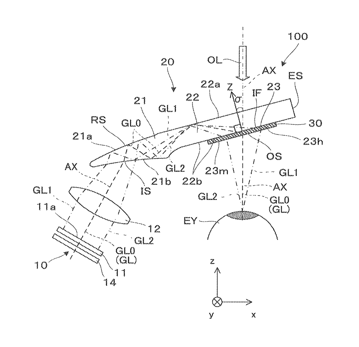
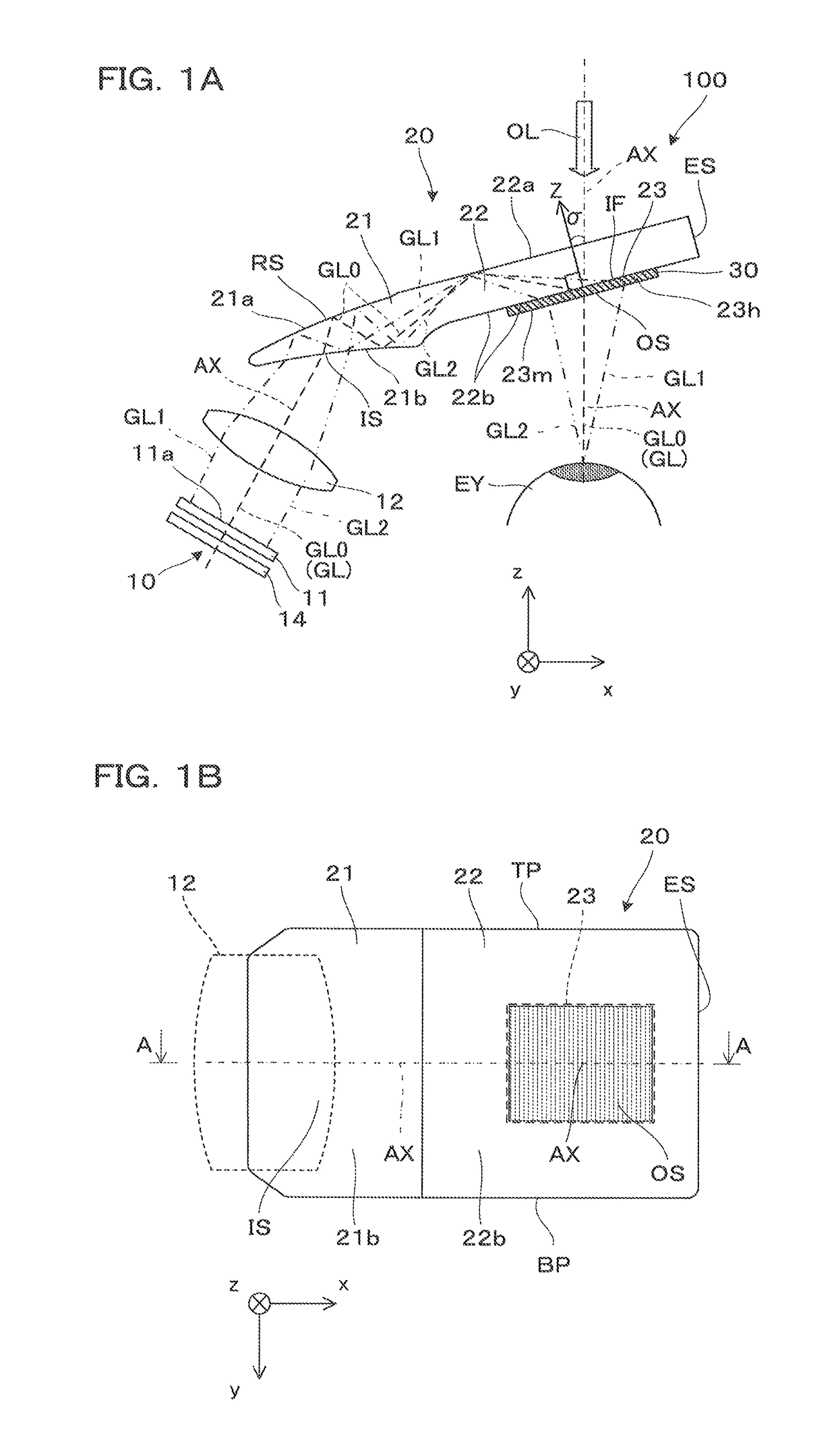
[0041]The virtual-image display device incorporating the light guide device in the first embodiment is explained with reference to FIGS. 1A and 1B. A virtual-image display device 100 is applied to a head mounted display and includes an image forming device 10 and a light guide device 20 as a set. Note that FIG. 1A corresponds to an A-A cross section of the light guide device 20 shown in FIG. 1B.

[0042]The virtual-image display device 100 causes an observer to recognize a video serving as a virtual image and causes the observer to observe an external image in a see-through manner. In the virtual-image display device 100, one set of the image forming device 10 and the light guide device 20 is usually provided for each of the right eye and the left eye of the observer. Howe...

second embodiment

[0089]A virtual-image display device incorporating a light guide device according to a second embodiment of the invention is explained. Note that the light guide device according to the second embodiment is obtained by partially changing the light guide device according to the first embodiment. Explanation is omitted concerning the common portions.

[0090]As shown in FIG. 11, the virtual-image display device 100 in this embodiment includes, as an element incidental to the light guide device 20, a shade member 60 that covers the external environment side of the light guide device 20. The shade member 60 is detachably fixed to the light guide device 20 via a not-shown frame. The shade member 60 has a polarization characteristic deviating to a predetermined direction. Specifically, the transmittance of P polarized light is higher than the transmittance of S polarized light. Consequently, the external light OL deviating to the P polarized light can be made incident on the light guide devi...

third embodiment

[0102]A virtual-image display device incorporating a light guide device according to a third embodiment of the invention is explained below. Note that the light guide device according to the third embodiment is obtained by partially changing the light guide device according to the first embodiment. Explanation is omitted concerning the common portions.

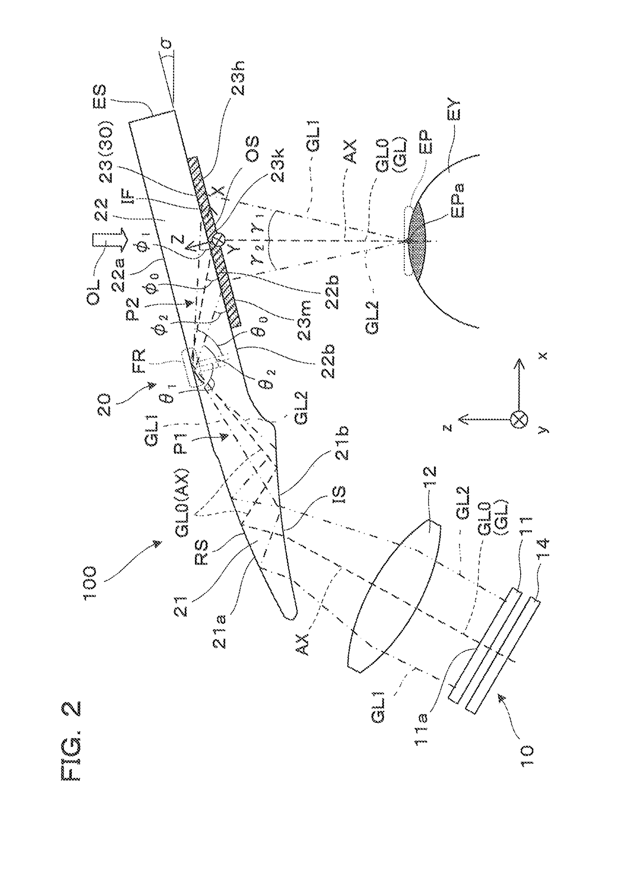
[0103]The structures of the light guide device and the virtual-image display device in the third embodiment are basically the same as the structures of the light guide device and the virtual-image display device in the first embodiment shown in FIGS. 1A, 1B, and 2. The reference to FIGS. 1A, 1B, and 2 is directly applied to the light guide device in the third embodiment.

[0104]An optical path of video light in the light guide device and the virtual-image display device in the third embodiment is the same as the optical path of the video light in the light guide device and the virtual-image display device in the first embodiment shown in...


PUM


Abstract

A light guide device includes an incident section, a parallel light guide body for light guide, and an emitting section. The emitting section includes a reflection unit formed by arraying a plurality of mirrors. The plurality of mirrors configuring the reflection unit are reflection elements having reflectance of P polarized light lower than reflectance of S polarized light. The plurality of mirrors configuring the reflection unit can be accompanied by wavelength plates to be adjacent to the mirrors.

Description

BACKGROUND[0001]1. Technical Field[0002]The present invention relates to a light guide device used in a head mounted display or the like mounted on a head and used and a virtual-image display device incorporating the light guide device.[0003]2. Related Art[0004]In recent years, as a virtual-image display device that enables formation and observation of a virtual image like a head mounted display, there have been proposed various virtual-image display devices of a type for guiding video lights received from a display element to the pupils of an observer with a light guide plate.[0005]For example, as a wearable display device that introduces a collimation image or the like into the visual field of an observer, there has been publicly known a wearable display device in which a large number of half mirrors (hereinafter referred to as “HMs” as well) inclined with respect to a principal plane and disposed in parallel to one another are incorporated in a light guide body having a parallel ...

Claims


Application Information

Patent Timeline
Patent Type & Authority Patents(United States)
IPC IPC(8): G02B27/01G02B27/28G02B5/30F21V8/00
CPCG02B5/3041G02B6/0035G02B6/0056G02B27/0172G02B27/285G02B6/0055G02B27/0101G02B2027/0118G02B2027/0125G02B2027/012G02B2027/0178G02B27/0018G02B27/30
Inventor KOMATSU, AKIRATOTANI, TAKAHIROTAKEDA, TAKASHITAKAGI, MASAYUKIMIYAO, TOSHIAKIMATSUKI, HAYATO
Owner SEIKO EPSON CORP
Why Eureka
Try Eureka