Apparatus for adjusting the tilt angle of an antenna

a technology for adjusting the tilt angle and antenna, which is applied in the direction of antennas, antenna details, electrical apparatus, etc., can solve the problems of high risk of electric shock, inconvenience and safety in performing the adjustment, and high risk of carrying out work, so as to ensure safety and facilitate the adjustment of the tilt angle of the antenna

Inactive Publication Date: 2018-09-18
TELEKOM MALAYSIA BERHAD
View PDF35 Cites 3 Cited by
  • Summary
  • Abstract
  • Description
  • Claims
  • Application Information

AI Technical Summary

Benefits of technology

[0009]Still another aspect of the present invention is to provide an apparatus that enables manual and automate adjusting of the tilt angle of an antenna.
[0010]Yet another aspect of the present invention is to provide an apparatus having a mechanism that makes adjusting of the tilt angle of an antenna easy.
[0011]Also another aspect of the present invention is to provide an apparatus that ensures safety of the person adjusting the tilt angle of an antenna on a pole.

Problems solved by technology

Whilst both prior arts enable the tilt of the antenna to be adjusted and locked at a desired position, the convenience and safety to perform the adjustment were overlooked.
However, the apparatus similarly requires manual rotating of the pole member and manual fastening of the bolt and nut assembly.
Not only is the adjusting work not convenient to be conducted as the person handling the work has to reach a position where he could reach the assembly which is usually mounted at a high position on a pole to rotate the downtilt member or pole handle and securing the tilt in position by fasteners, it also poses danger to the person carrying out the work due to the height of the antenna, the exposure to electromagnetic radiation as well as the high risk of electric shock.

Method used


Image

  • Apparatus for adjusting the tilt angle of an antenna
  • Apparatus for adjusting the tilt angle of an antenna
  • Apparatus for adjusting the tilt angle of an antenna

Examples


Embodiment Construction

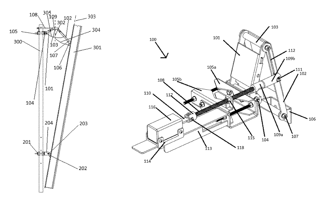
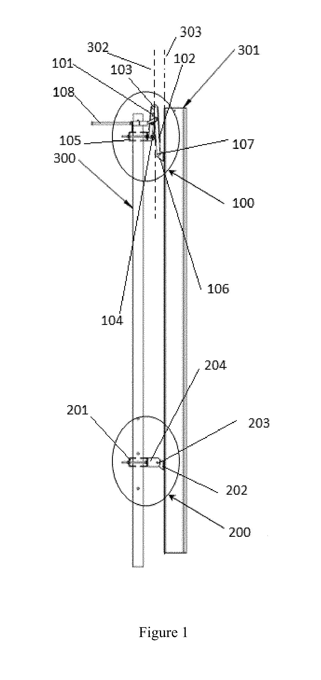
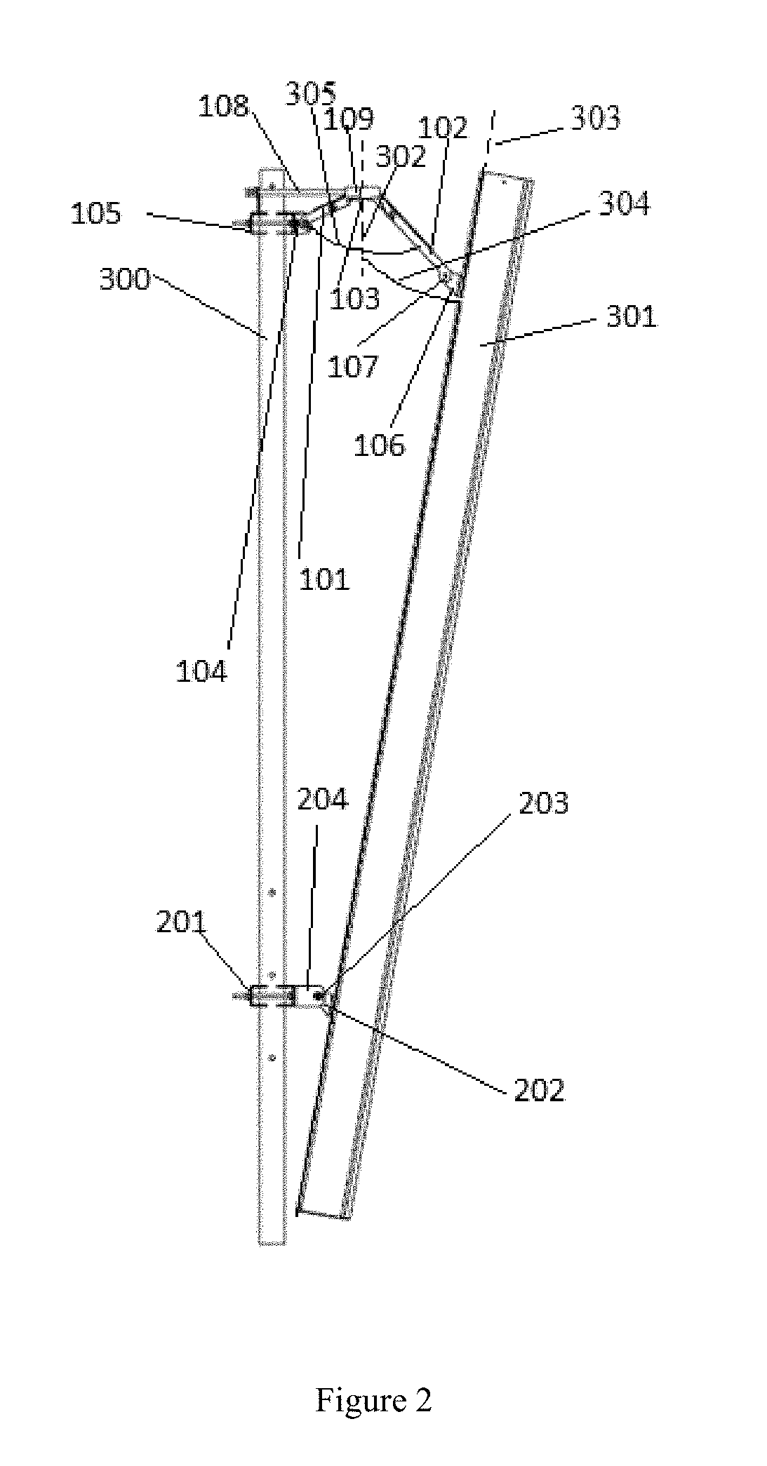
[0023]The present invention discloses an apparatus for adjusting a tilt angle (304) of a vertically positioned antenna (301) on a pole (300) comprising a top mounting assembly (100) formed by a first link (101) and a second link (102) that has a top edge and a bottom edge each, the top edges of both links (101, 102) are pivotally connected together by a first hinge (103) such that the second link (102) is rotatable about the first hinge (103) in relative to the first link (101) to adjust an angle (305) between the links (101, 102) while the bottom edge of the first link (101) has a clamp (105) that is pivotally connected to its outer surface by a second hinge (104) for affixing the top mounting assembly (100) to the upper portion of the pole (300) and the bottom edge of the second link (102) has an antenna bracket (106) at its outer surface for affixing the top mounting assembly (100) to the upper portion of the antenna (301), wherein the second link (102) is fabricated with a slot ...


PUM


Abstract

An apparatus for adjusting a tilt angle of a vertically positioned antenna on a pole that includes a top mounting assembly formed by a first link and a second link, the first and second link each including a top edge and a bottom edge, the top edges of the first link and the second link are pivotally connected together by a first hinge such that the second link is rotatable about the first hinge in relation to the first link to adjust an angle between the first link and the second link.

Description

FIELD OF INVENTION[0001]The present invention relates to an apparatus for adjusting the tilt angle of a vertically positioned antenna on a pole.BACKGROUND OF THE INVENTION[0002]Antennas mounted high up on poles are protected from interference from other neighboring electronic devices and also reduces the exposure to electromagnetic fields for human and animals. It is however important that these antennas are configured in an accurate inclination in relative to an axis to direct and concentrate irradiation to a desired area.[0003]An example of antenna mounting assembly allow tilt adjustment of the antenna is U.S. Patent Application No. 2011 / 0168855 that depicts a rotating mounting assembly comprising an extension member and a downtilt member being coupled together by a plurality of revolving nutplate hinges such that the downtilt member rotates about the nutplate hinges in relative to the extension member. Each nutplate hinge is formed by an extension flange hinge tab and a downtilt ...

Claims


Application Information

Patent Timeline
Patent Type & Authority Patents(United States)
IPC IPC(8): H01Q1/12H01Q3/06
CPCH01Q1/1228H01Q1/1264H01Q3/06H01Q1/125
Inventor ASROKIN, AZHARI BINBASRI, RIZAL HELMY BINABAS, ANAS BINJAMLUS, NORMAN BIN
Owner TELEKOM MALAYSIA BERHAD
Why Eureka
Try Eureka