Flow-rate control device and flow-rate control program

a flow-rate control and flow-rate setting technology, applied in the direction of flow control using electric means, electric programme control, instruments, etc., can solve the problems of difficult to track the real flow-rate value to the flow-rate setting value, difficult to achieve accurate reproduction, and difficult to achieve the effect of ideally shaped response characteristics of real flow-rate values during transient respons

Active Publication Date: 2018-09-25
HORIBA STEC CO LTD
View PDF20 Cites 0 Cited by
  • Summary
  • Abstract
  • Description
  • Claims
  • Application Information

AI Technical Summary

Benefits of technology

[0021]According to the flow-rate control device of the present invention as described above, the feedback control unit is configured to output a flow-rate feedback value based on the deviation between a flow-rate simulation value output based on the sensor model and in which a time delay is reflected and a flow-rate measurement value that is measured with the flow-rate sensor, thus enabling flow-rate feedback that reflects the time delay of the flow-rate sensor. Accordingly, the flow-rate feedback value at the start of flow-rate control will be substantially zero and the degree of opening of the valve is controlled by only the flow-rate feedforward value, thus enabling a faster response to the real flow-rate value without causing overshoot or the like. Furthermore, the time delay is reproduced by starting output of the flow-rate simulation value based on the sensor model and the flow-rate setting value after the flow-rate measurement value reaches a predetermined threshold, thus enabling the time delay to be accurately reproduced with a simple sensor model and the response characteristics to be improved.

Problems solved by technology

However, even with the two degree-of-freedom flow-rate control device described in Patent Document 1, it is difficult to ideally shape the response characteristics of the real flow-rate value during the transient response.
Thus, when a time delay exists in the flow-rate measurement value that is measured with the flow-rate sensor, it is difficult to track the real flow-rate value to the flow-rate setting value due to problems such as overshoot occurring or control becoming unstable when gain is increased.
Such control-related problems that occur due to time delays become particularly marked in the case where the flow-rate sensor is a thermal flow-rate sensor.
That is, it is not currently possible to limit feedback control to when conditions are suitable in the case of performing two degree-of-freedom flow-rate control.

Method used


Image

  • Flow-rate control device and flow-rate control program
  • Flow-rate control device and flow-rate control program
  • Flow-rate control device and flow-rate control program

Examples


Embodiment Construction

[0048]Configuration of Present Embodiment

[0049]A flow-rate control device according to one embodiment of the present invention will be described with reference to the drawings.

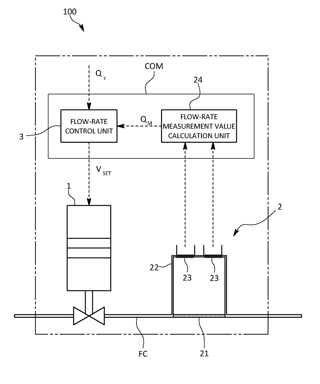
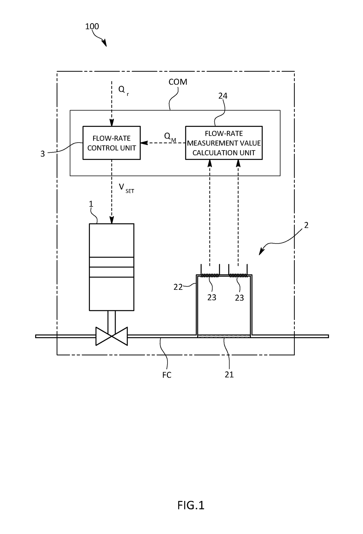
[0050]The flow-rate control device of the present embodiment is a mass flow controller 100 that is used in order to introduce a gas containing a substance to be vapor-deposited onto a substrate into a chamber in which vapor deposition is performed at a predetermined flow-rate setting value Qr in a semiconductor manufacturing process, for example.

[0051]This mass flow controller 100 has an inlet and an outlet that are attached to a flow channel extending to the chamber during the semiconductor manufacturing process as shown in FIG. 1, and controls the flow rate of gas that flows through the flow channel. More specifically, the mass flow controller 100 is provided with an internal flow channel FC, a valve 1 provided in the internal flow channel FC, a flow-rate sensor 2 that measures the flow rate of the fluid tha...


PUM


Abstract

A flow-rate control unit is constituted by a sensor model storage unit, a flow-rate simulation value output unit that outputs a flow-rate simulation value which is a flow-rate value that the sensor model outputs when a flow-rate setting value is input, a feedback control unit that outputs a flow-rate feedback value based on a deviation between a flow-rate measurement value and the flow-rate simulation value, and a valve control unit that controls a valve application voltage that is applied to a valve based on the flow-rate feedback value and a flow-rate feedforward value that is calculated from the flow-rate setting value, and the flow-rate simulation value output unit is configured to output the flow-rate simulation value in a state where a predetermined time delay exists with respect to the flow-rate setting value.

Description

TECHNICAL FIELD[0001]The present invention relates to a flow-rate control device and a flow-rate control program that are for controlling the flow rate of a fluid.BACKGROUND ART[0002]A flow-rate control device that is used in a semiconductor manufacturing process is required to quickly track the real flow-rate value to a flow-rate setting value that is set by a user.[0003]In response to this requirement, a flow-rate control device that is shown in Patent Document 1, for example, is provided with a flow-rate sensor, a valve, and a flow-rate control unit that controls the flow rate using the valve, with the flow-rate control unit being configured to control the degree of opening of the valve using two degree-of-freedom control that combines feedback control according to a flow-rate measurement value that is output from the flow-rate sensor and feedforward control according to the flow-rate setting value that is set.[0004]That is, this flow-rate control device is intended to track the ...

Claims


Application Information

Patent Timeline
Patent Type & Authority Patents(United States)
IPC IPC(8): G05D7/00G05D7/06
CPCG05D7/0635G05B17/02G05B19/04
Inventor TAKIJIRI, KOTAROSHIMIZU, KEITA
Owner HORIBA STEC CO LTD
Why Eureka
Try Eureka