Electric motor with a permanent magnet embedded rotor with curved magnets and magnet accommodation holes of varying radiuses

a permanent magnet and electric motor technology, applied in the direction of dynamo-electric machines, magnetic circuit rotating parts, magnetic circuit shapes/forms/construction, etc., can solve the problems of increasing the cost of electric motors and the cost of earth permanent magnets, and achieve the effect of increasing the demagnetization resistance against the demagnetizing field and increasing the output of the motor without reducing the torqu

Active Publication Date: 2018-09-25
MITSUBISHI ELECTRIC CORP
View PDF43 Cites 2 Cited by
  • Summary
  • Abstract
  • Description
  • Claims
  • Application Information

AI Technical Summary

Benefits of technology

[0015]According to one embodiment of the present invention, such effects are obtained that the output of the motor is increased without reducing the torque by increasing the demagnetization resistance against the demagnetizing field.

Problems solved by technology

However, the rare-earth permanent magnets are expensive, which leads to increase in cost of the electric motor.

Method used


Image

  • Electric motor with a permanent magnet embedded rotor with curved magnets and magnet accommodation holes of varying radiuses
  • Electric motor with a permanent magnet embedded rotor with curved magnets and magnet accommodation holes of varying radiuses
  • Electric motor with a permanent magnet embedded rotor with curved magnets and magnet accommodation holes of varying radiuses

Examples


first embodiment

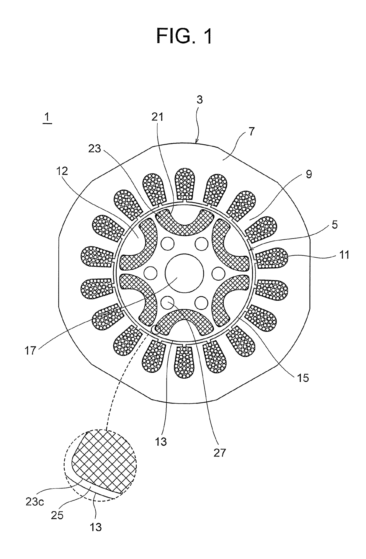
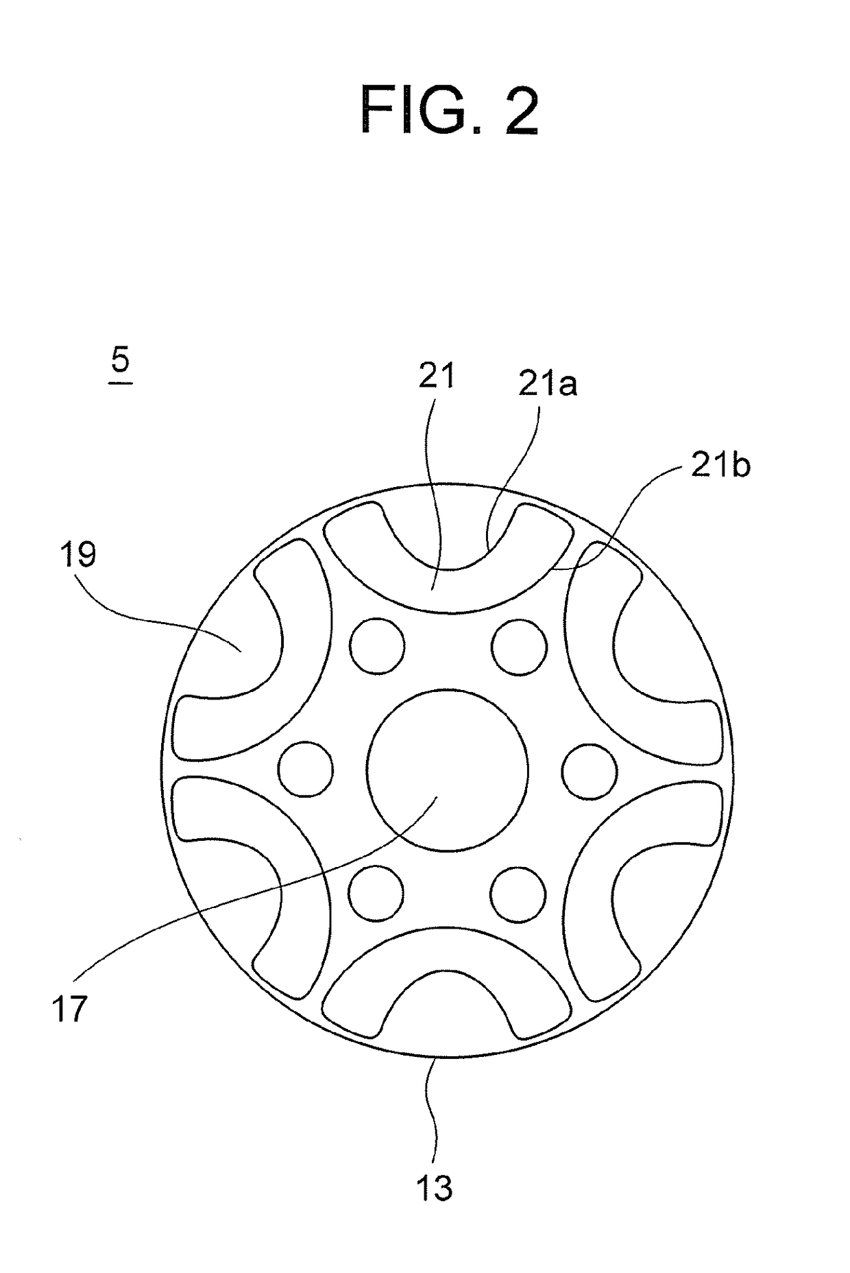
[0024]FIG. 1 is a sectional view of an interior permanent magnet motor according to a first embodiment of the present invention, specifically, a view illustrating a cross section having a rotary shaft of a rotator as the normal. Further, FIG. 2 is a sectional view of a rotator core illustrated in FIG. 1 under a state in which permanent magnets are not set in magnet accommodating holes. FIG. 3 is a partially enlarged view illustrating a dimensional feature of the magnet accommodating hole of FIG. 2. FIG. 4 is a sectional view of a rotator under a state in which the permanent magnets are set in the magnet accommodating holes in FIG. 2. FIG. 5 is a view illustrating an example of magnetic orientation of the permanent magnet.

[0025]In FIG. 1, an interior permanent magnet motor 1 according to the first embodiment includes a stator 3 and a rotator 5. The stator 3 includes a stator core 7 having an annular shape, a plurality of teeth 9 formed at equiangular pitches in a circumferential dire...

second embodiment

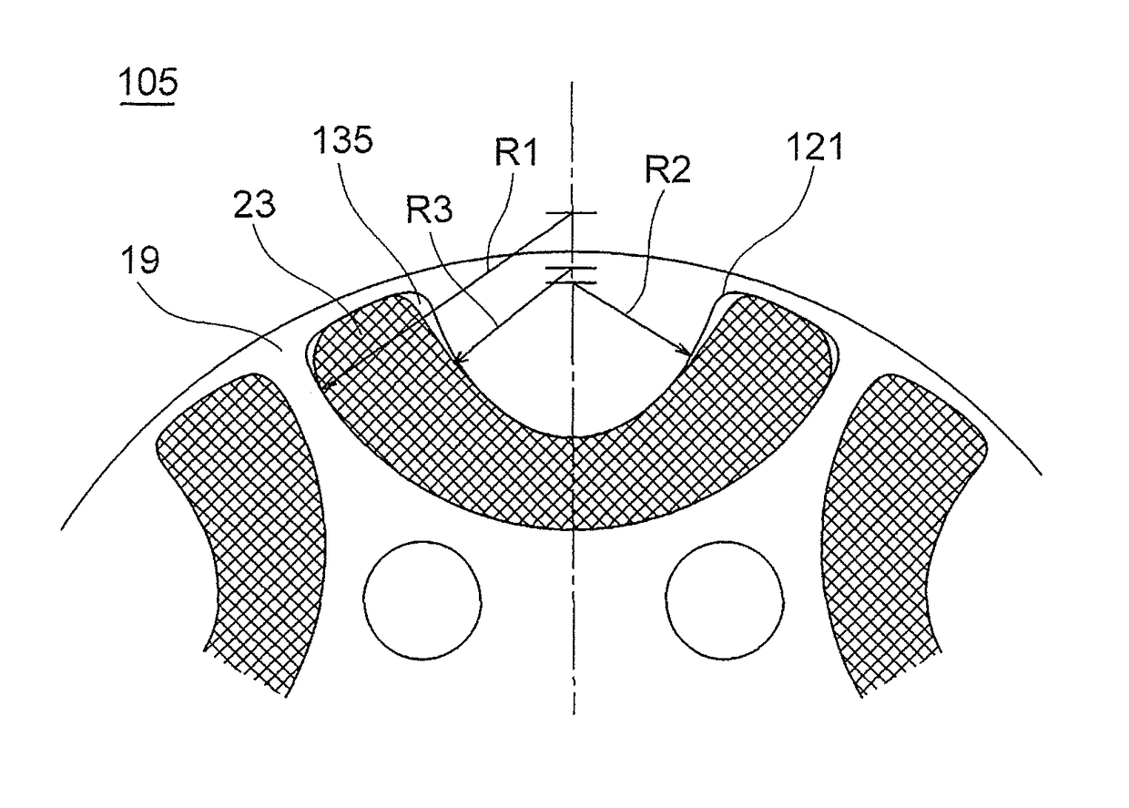
[0043]Next, a second embodiment of the present invention is described with reference to FIGS. 6 and 7. Note that, the second embodiment is similar to the above-mentioned first embodiment except for the part described below. FIG. 6 is a view illustrating the same mode as FIG. 4 according to the second embodiment. FIG. 7 is a partially enlarged view illustrating a dimensional feature of a magnet accommodating hole of FIG. 6.

[0044]As illustrated in FIGS. 6 and 7, in the second embodiment, a magnet accommodating hole 121 and the permanent magnet 23 are formed so that, when the curvature radius of the arc defining line on the outer side of the recess of the magnet accommodating hole 121 (radius of the arc on the center side of the rotator core 19) is represented by R1, the curvature radius of the inner arc defining line of the magnet accommodating hole 121 (radius of the arc on the outer peripheral side of the rotator core 19) is represented by R2, and a radius of the arc on the outer pe...


PUM


Abstract

An interior permanent magnet motor capable of increasing an output of a motor without reducing torque by increasing demagnetization resistance. The interior permanent magnet motor includes a rotator including a rotator core, and a stator. The rotator core includes a plurality of magnet accommodating holes and a plurality of permanent magnets. The thickness in the short-side direction of each of the magnet accommodating holes is minimum at the center portion of the magnetic pole, and is gradually increased toward the radially outer side of the rotator core. At least the thickness in the short-side direction of the permanent magnet at the center portion of the magnetic pole is equal to the thickness in the short-side direction of the magnet accommodating hole at the center portion of the magnetic pole.

Description

CROSS REFERENCE TO RELATED APPLICATION[0001]This application is a U.S. national stage application of PCT / JP2013 / 075425 filed on Sep. 20, 2013, which claims priority to Japanese patent application No. 2012-074421, filed on Sep. 24, 2012, the contents of which are incorporated herein by reference.TECHNICAL FIELD[0002]The present invention relates to an interior permanent magnet motor in which permanent magnets are embedded inside a rotator core.BACKGROUND ART[0003]In recent years, due to increase in awareness of energy saving, there have been proposed a large number of permanent magnet electric motors configured to use rare-earth permanent magnets having high coercivity in a rotator, to thereby realize high efficiency. However, the rare-earth permanent magnets are expensive, which leads to increase in cost of the electric motor. Therefore, in a rotator of a related-art general interior permanent magnet motor, sintered ferrite magnets are used instead of the rare-earth permanent magnet...

Claims


Application Information

Patent Timeline
Patent Type & Authority Patents(United States)
IPC IPC(8): H02K1/27
CPCH02K1/2766H02K2213/03
Inventor BABA, KAZUHIKONIGO, MASAHIROTSUCHIDA, KAZUCHIKA
Owner MITSUBISHI ELECTRIC CORP
Why Eureka
Try Eureka