
Clutch device

a technology of clumping and locking rod, which is applied in the direction of friction clutches, mechanical actuated clutches, and clumps, can solve problems such as bolt loosening, and achieve the effect of suppressing bolt loosening

Active Publication Date: 2021-06-03
EXEDY CORP
View PDF0 Cites 0 Cited by
  • Summary
  • Abstract
  • Description
  • Claims
  • Application Information

AI Technical Summary

Benefits of technology

The patent describes a device that prevents bolt loosening between members without reducing the torque transmitted on fastening surfaces. The device includes an anti-slip member that fits in two fitting holes, which helps prevent slip between the fastening surfaces. The device also makes it easier to assemble the support plate and clutch center, improving the overall assembly property. The technical effect of this device is to suppress bolt loosening and improve the assembly of the support plate and clutch center.

Problems solved by technology

However, when a clutch device has a cam mechanism, a bolt may loosen.

Method used


Image

  • Clutch device
  • Clutch device
  • Clutch device

Examples


modification 1

[0079]In the above embodiment, the anti-slip member 50 has a cylindrical shape, but the present invention is not limited to this. For example, as illustrated in FIG. 7, the anti-slip member 50 may have a substantially prismatic shape, and one surface of the prism may be along the surface of the bolt 40. In this case, one or more anti-slip members 50 are arranged around each bolt 40 with respect to one bolt 40. The size of the anti-slip member 50 is not particularly limited as long as the first fitting hole 19d and the second fitting hole 32d can be fitted together.

modification 2

[0080]The anti-slip member 50 may have a substantially plate shape. In this case, the surface, in which the anti-slip member 50 extends, contacts the surface of the bolt 40 in the axial direction.

modification 3

[0081]In the above embodiment, the seat surface of the bolt 40 is arranged on the support plate 10 side, but the present invention is not limited to this. For example, the seating surface of the bolt 40 may be arranged on the clutch center 30 side. In this case, the bolt 40 is screwed onto the support plate 10. In this case, it is possible to prevent the bolt 40 from loosening during the operation of the slipper cam mechanism 61.


PUM


Abstract

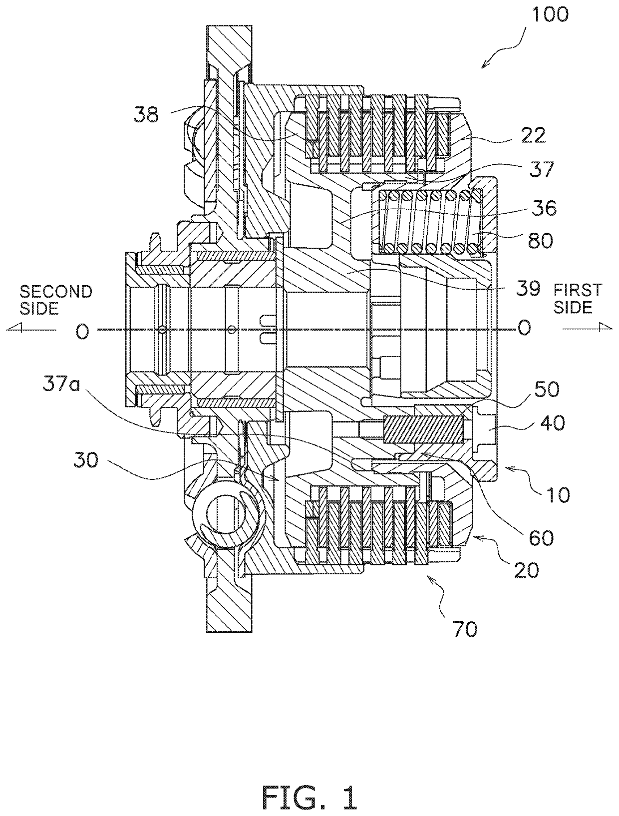
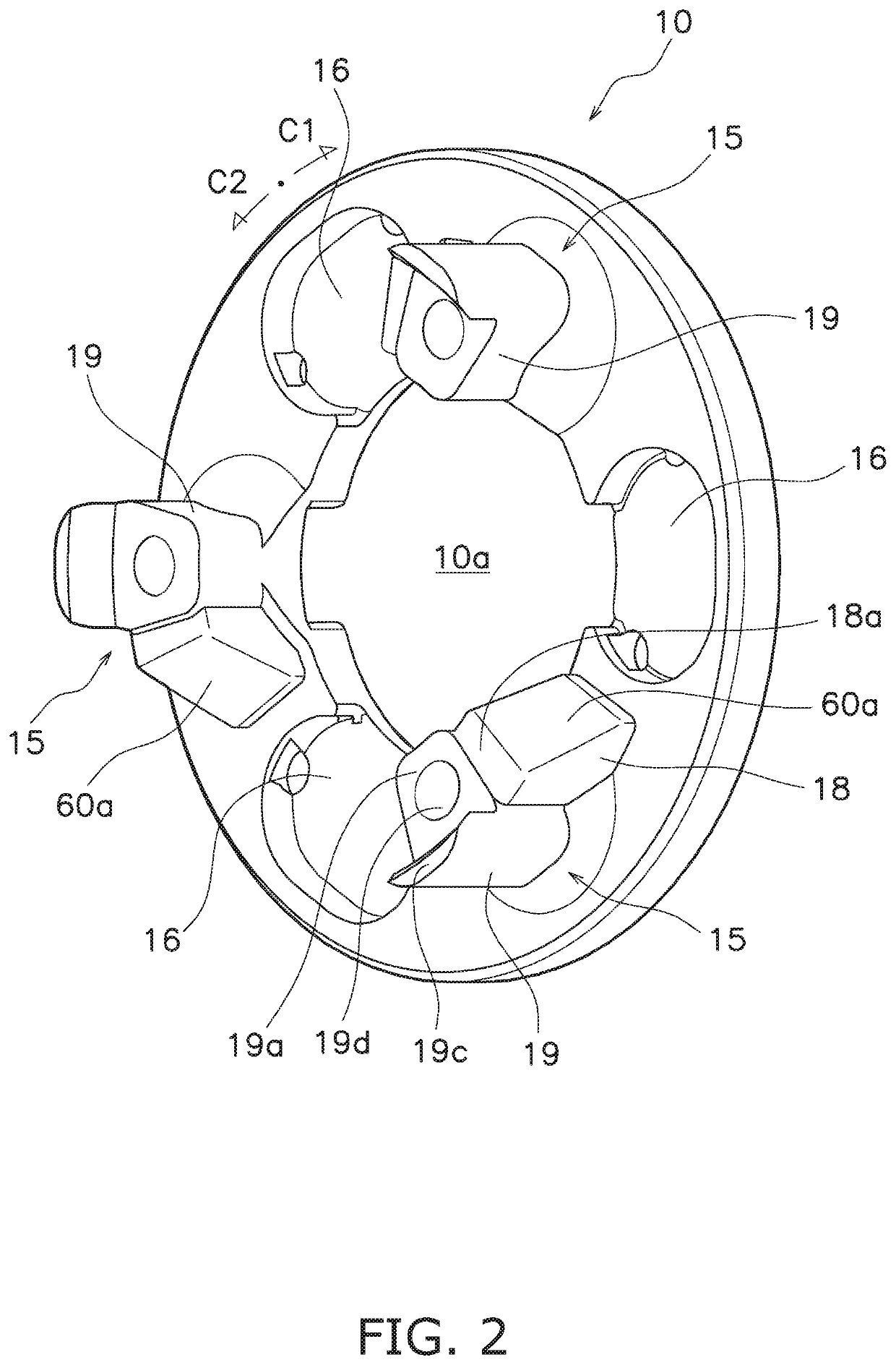
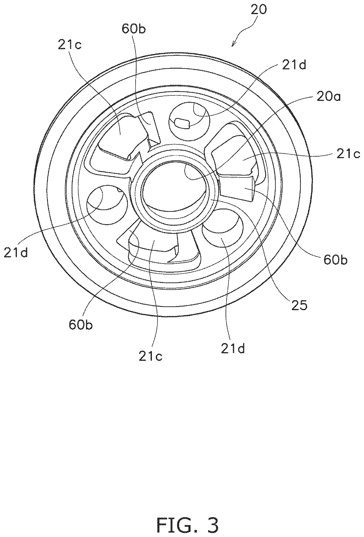
A clutch device includes a first rotor, a second rotor, a third rotor, at least one bolt, at least one anti-slip member, and a cam mechanism. The first rotor has a first cam surface and a first fitting hole extending in an axial direction. The second rotor has a second cam surface and a second fitting hole. The second cam surface presses the first cam surface in a circumferential direction. The second fitting hole faces the first fitting hole and extends in the axial direction. The third rotor is fixed to the first rotor. The bolt connects the first rotor and the third rotor. The anti-slip member fits into the first and second fitting holes. The cam mechanism includes the first cam surface and the second cam surface, and moves the second rotor in the axial direction when relative rotation occurs between the first rotor and the second rotor.

Description

CROSS-REFERENCE TO RELATED APPLICATIONS[0001]This application claims priority to Japanese Patent Application No. 2019-218993, filed on Dec. 3, 2019. The contents of that application are incorporated by reference herein in their entirety.TECHNICAL FIELD[0002]The present invention relates to a clutch device.BACKGROUND ART[0003]For example, in motorcycles, such as buggies, a clutch device is used to transmit or cut off power from an engine to a transmission. This clutch device includes a clutch center, a clutch portion for transmitting and disconnecting power between them, and a pressure plate for pressing the clutch portion. The clutch center is connected to the support plate by bolts.[0004]There has been proposed a clutch device provided with a cam mechanism for increasing or decreasing a pressing force on a clutch portion by relative rotation of the pressure plate and the support plate (Japanese Patent Laid-Open No. 2017-101810)).BRIEF SUMMARY[0005]However, when a clutch device has ...

Claims


Application Information

Patent Timeline
IPC IPC(8): F16D13/75F16D23/12
CPCF16D13/752F16D13/52F16D2023/123F16D23/12F16D2013/565
Inventor KITAZAWA, HIDENORIMANO, OSAMU
Owner EXEDY CORP
Learn More