
Rotor of rotary electric machine, and production method therefor

A technology for a rotating electrical machine and a manufacturing method, which can be used in the manufacture of stator/rotor bodies, electromechanical devices, electrical components, etc., and can solve problems such as increasing costs

Inactive Publication Date: 2010-03-24
TOYOTA JIDOSHA KK
View PDF1 Cites 7 Cited by
  • Summary
  • Abstract
  • Description
  • Claims
  • Application Information

AI Technical Summary

Problems solved by technology

However, both approaches significantly increase the cost

Method used


Image

  • Rotor of rotary electric machine, and production method therefor
  • Rotor of rotary electric machine, and production method therefor
  • Rotor of rotary electric machine, and production method therefor

Examples


Embodiment Construction

[0032] Embodiments of the present invention will be described in detail below with reference to the accompanying drawings. The same or corresponding parts are given the same reference numerals in the drawings, and descriptions thereof will not be repeated.

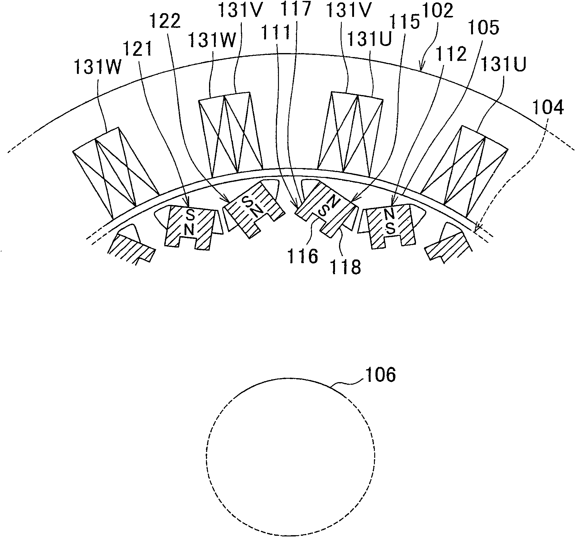
[0033] figure 1 is a sectional view for explaining the positions of the rotor and the stator of the motor according to the embodiment of the present invention.

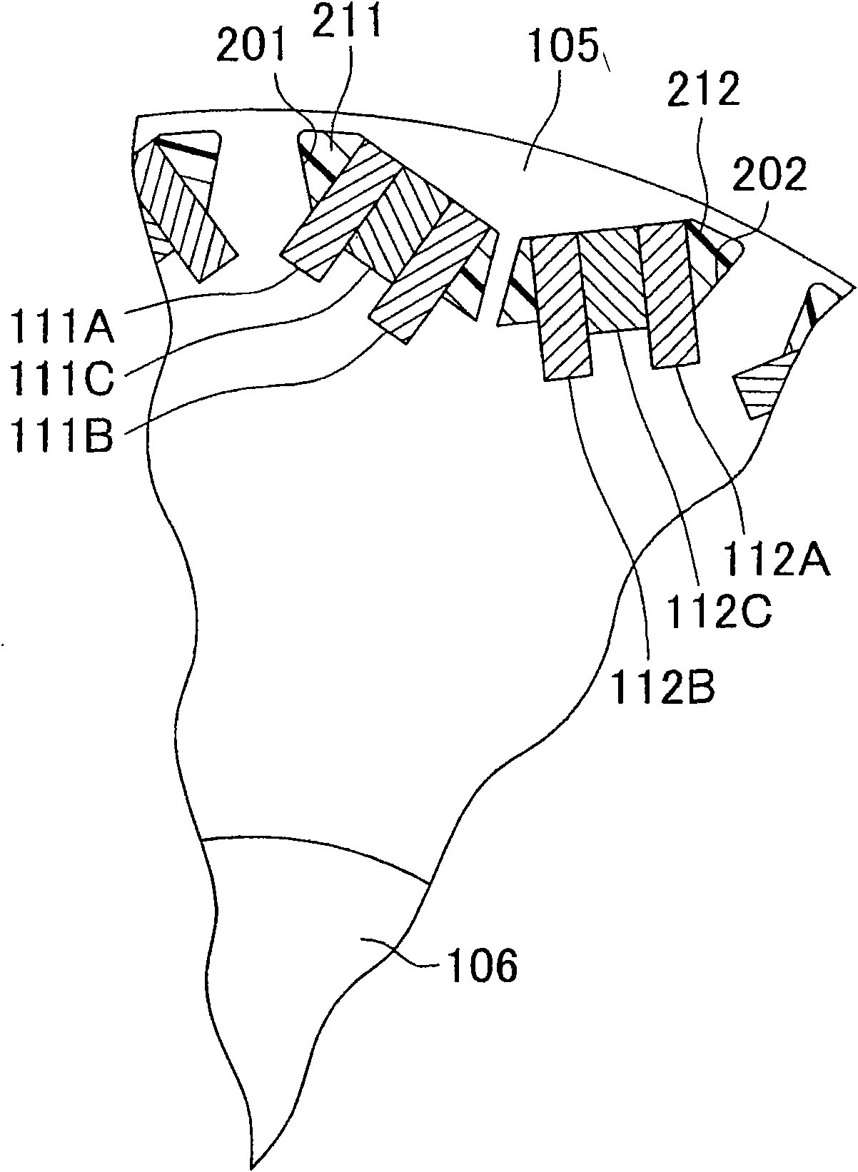
[0034] refer to figure 1 , an electric motor as a type of rotating electric machine includes a stator 102 and a rotor 104 . The rotor 104 includes a shaft 106 and a rotor core 105 disposed around the shaft 106 . figure 1 A portion corresponding to one-sixth of the entire circumference of the rotor and stator is shown in detail.

[0035] The rotor core 105 is formed of, for example, laminated electromagnetic steel sheets. figure 1 The rotor 104 in has 12 poles. For each pole, a pair of magnets arranged in a V shape is used. The rotor core 105 is provided...


PUM


Abstract

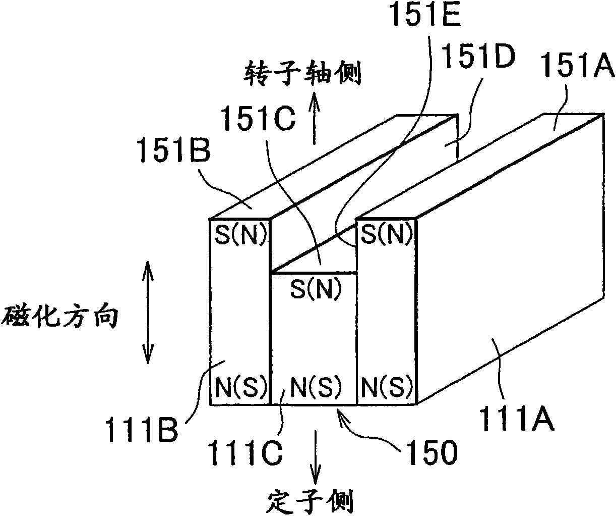
A rotor (104) includes a rotor core (105) and permanent magnets (111, 112, 121, 122) embedded in the rotor core (105). The permanent magnet (111) includes a first surface that is a flat surface facinga stator side, and a second surface that is opposite from the first surface. A center position of a middle portion of the permanent magnet (111) which is a center in the magnetization direction of the permanent magnet (111) is positioned in a stator side of a center position of two opposite end portions of the permanent magnet (111) in a direction orthogonal to the magnetization direction which is a center in the magnetization direction.

Description

technical field [0001] The present invention relates to a rotor of a rotating electrical machine and a method of manufacturing the same. More specifically, the present invention relates to a permanent magnet embedded rotor and a manufacturing method thereof. Background technique [0002] A rotating electrical machine with a permanent magnet-embedded rotor is a high-output motor utilizing magnetic torque and reluctance torque. In recent years, rotating electric machines having permanent magnet embedded rotors have been used in driving devices of vehicles such as electric vehicles, hybrid vehicles, and the like. [0003] Japanese Patent Application Publication No. 2006-166625 (JP-A-2006-166625) describes a rotating electrical machine capable of increasing rotor torque by reducing magnetic resistance. [0004] The rotary electric machine has a rotor in which magnets are attached to a rotor core through opposite end surfaces of which a rotating shaft passes; and a stator in wh...

Claims


Application Information

Patent Timeline
Patent Type & Authority Applications(China)
IPC IPC(8): H02K1/27H02K15/03
CPCH02K1/2766Y10T29/49012
Inventor 小暮智也金田敬右平贺雅明
Owner TOYOTA JIDOSHA KK
Learn More