Split type combined permanent magnet brushless motor for electric vehicle

A permanent magnet brushless motor, electric vehicle technology, used in electric vehicles, motors, synchronous motors with static armatures and rotating magnets, etc. Mechanical strength reduction and other issues, to ensure the power density and torque density, is conducive to high-speed cruising ability, improve the effect of weak magnetic ability

Active Publication Date: 2016-02-10
JIANGSU UNIV
View PDF4 Cites 7 Cited by
  • Summary
  • Abstract
  • Description
  • Claims
  • Application Information

AI Technical Summary

Problems solved by technology

However, since the reluctance torque accounts for the main part of the output torque, the torque ripple of the permanent magnet assisted synchronous reluctance motor is relatively large
In the document "Rotorstructure in 50kW spoke-type interior permanent magnet synchronous motor with ferrite permanent magnets for automotive applications" (published in IEEE Energy Conversion Congress and Exposition in 2013, pages 606-613), the power density of the motor is improved by adding an air gap to the traditional spoke-shaped ferrite motor rotor, but the reluctance torque is used The mechanical strength of the machine is also reduced, and there is a risk when running at high speed
In order to ensure a certain power density, ferrite permanent magnet motors generally need to use a large amount of ferrite permanent magnet materials, which will reduce the direct-axis inductance of the motor, thereby affecting the motor's ability to increase speed with weak magnetic field, and is not suitable for high-speed motors. run

Method used


Image

  • Split type combined permanent magnet brushless motor for electric vehicle
  • Split type combined permanent magnet brushless motor for electric vehicle
  • Split type combined permanent magnet brushless motor for electric vehicle

Examples


Embodiment Construction

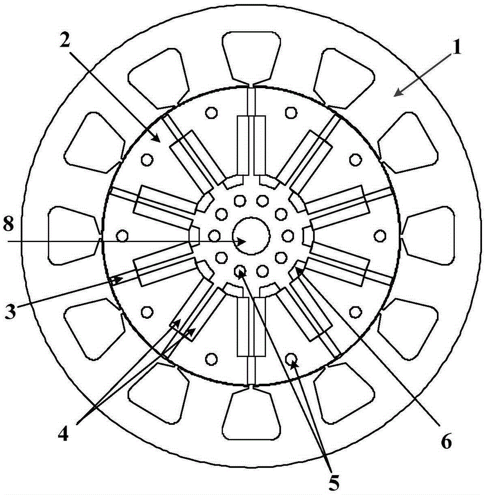
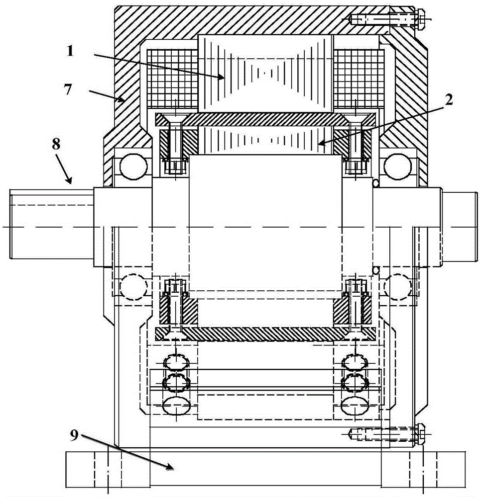
[0030] see figure 1 , figure 2 and image 3, the present invention includes a stator 1, a rotor 2, a rotating shaft 8 and an end cover 7, the stator 1 and the end cover 7 are fixedly connected together, and the end cover 7 is fixedly installed on the base 9. The rotor 2 is coaxially located inside the stator 1, and the center of the rotor 2 has a slot for placing the rotating shaft 8, and the rotor 2 is driven to rotate by the rotating shaft 8. Both the stator 1 and the rotor 2 are formed by laminating silicon steel sheets with a thickness of 0.35 mm, and the lamination coefficient is 0.95. The rotating shaft 8 is composed of non-magnetic materials. There is an air gap between the inner wall of the stator 1 and the outer wall of the rotor 2, and the thickness of the air gap is related to the power level of the motor, the selected permanent magnet material, and the processing and assembly process of the stator 1 and rotor 2.

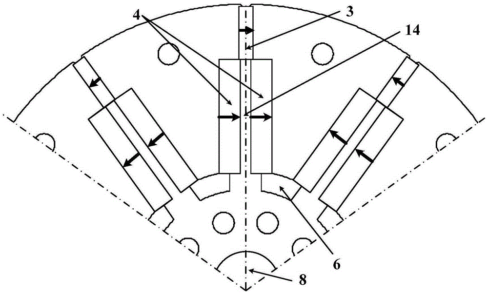
[0031] Each pole of the rotor 2 is fixedly inla...


PUM


Abstract

The invention discloses a split type combined permanent magnet brushless motor for an electric vehicle. A rotor is coaxially positioned in the internal of a stator; a rectangular neodymium iron boron permanent magnet steel and two same rectangular ferrite permanent magnet steels are fixedly embedded in each pole of the rotor; the neodymium iron boron permanent magnet steels are close to air gaps and are symmetrical relative to the central line of the rotor poles; the two ferrite permanent magnet steels are close to a rotation shaft, are distributed on the two sides of the central line of the rotor poles and are symmetrical relative to the central line of the rotor poles; a magnetic conductive bridge is between the two ferrite permanent magnet steels; the permanent magnet steel on each pole is magnetized along the tangential direction of the circumference; the magnetizing directions on the same pole are the same, and the magnetizing directions on the adjacent two poles are opposite; the rare earth permanent magnet material and the non-rare-earth ferrite permanent magnet material are adopted at the same time; on the basis of ensuring the power density and the torque density of the permanent magnet motor with a small amount of rare earth, the cost of the motor is reduced by more than 50%; and in addition, the requirements on the torque and the power in the electric vehicle applications can be met on the premise of keeping the relatively high power density and the torque density.

Description

technical field [0001] The invention relates to a permanent magnet synchronous motor, which belongs to the field of motor manufacturing and control, in particular to a permanent magnet synchronous motor suitable for traction hybrid vehicles, electric vehicles and other applications that require wide speed regulation, high efficiency, high power density and other drive performance requirements. Magnetic brushless motor. Background technique [0002] With the improvement of the performance of permanent magnets, rare earth permanent magnet motors based on NdFeB have been widely used in hybrid vehicles, electric vehicles and other fields due to their advantages such as high power density and high efficiency. In recent years, the over-exploitation of rare earth minerals has not only greatly reduced the reserves of rare earths, but also caused serious damage to the ecological environment. In order to protect rare earth resources and the increase in demand for rare earth permanent...

Claims


Application Information

Patent Timeline
Patent Type & Authority Applications(China)
IPC IPC(8): H02K21/14H02K21/16H02K1/27
CPCY02T10/64
Inventor 朱孝勇王琳全力杜怿
Owner JIANGSU UNIV
Why Eureka
Try Eureka