Eureka AIR delivers breakthrough ideas for toughest innovation challenges, trusted by R&D personnel around the world.

Multi-phase switching regulator and control circuit and control method thereof

a multi-phase switching regulator and control circuit technology, applied in the direction of dc-dc conversion, power conversion systems, instruments, etc., can solve the problems of unstable multi-phase switching regulator, unstable output voltage,

Active Publication Date: 2018-10-09
RICHTEK TECH
View PDF2 Cites 7 Cited by
  • Summary
  • Abstract
  • Description
  • Claims
  • Application Information

AI Technical Summary

Benefits of technology

The patent describes a way to change the duty ratio of a signal in a gradual manner using a circuit called a ramp signal setting. This helps to gradually increase the output of the signal and control its timing. This technology can be useful in various applications, such as in the control of electric motors.

Problems solved by technology

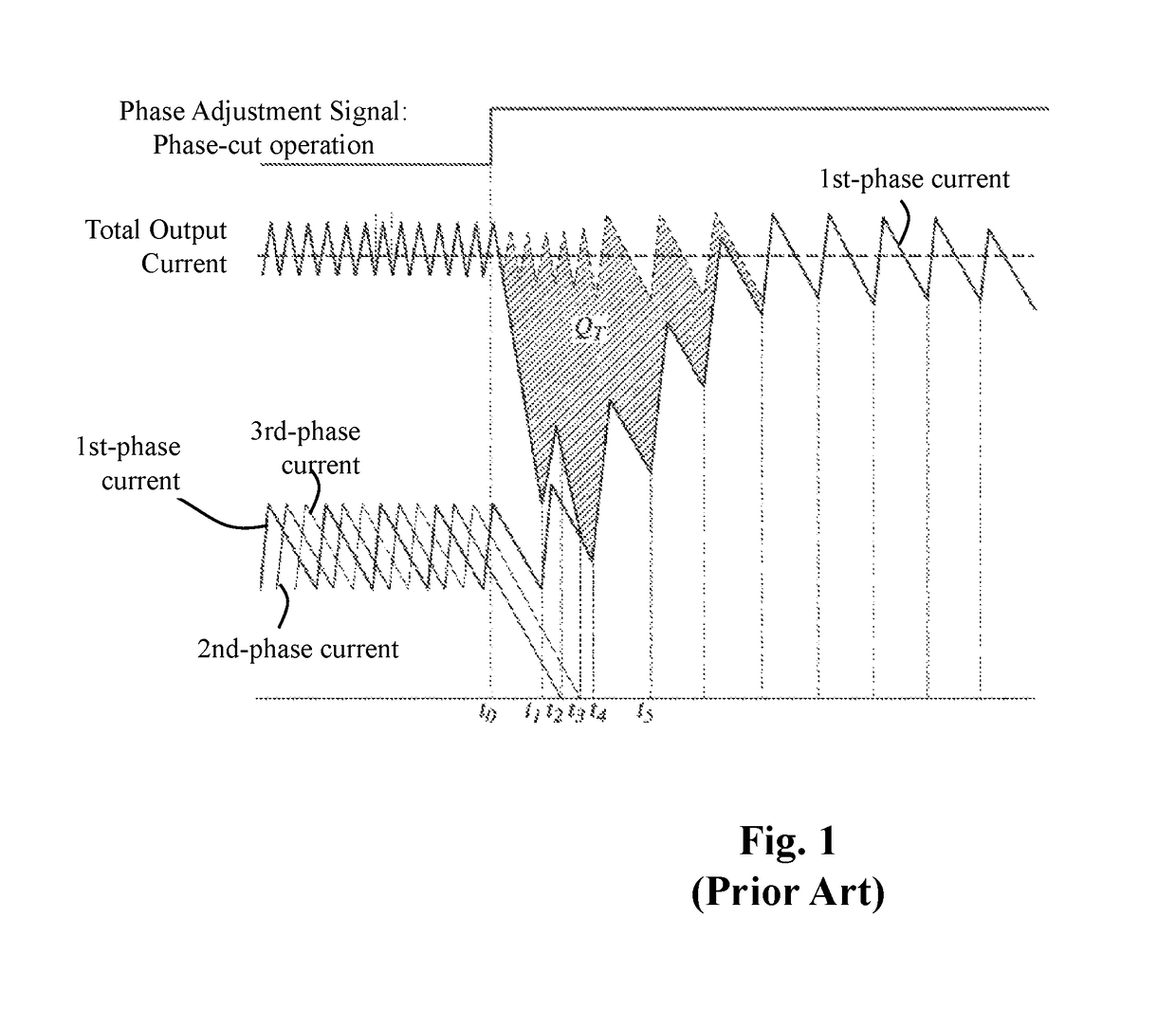
However, an undesirable transient voltage undershoot or overshoot is a problem in the conventional multi-phase switching regulator when its phase number is being adjusted, i.e. when it is in “phase add” or “phase cut” operation.
As shown in FIG. 1, this will result in a sudden drop of the total output current Iout, thereby causing an undesirable undershoot of the output voltage during the transition; the insufficient amount of the output voltage is equal to the area QT.
The sudden drop (i.e., undershoot) of the output voltage causes instability of the multi-phase switching regulator and other problems.
On the other hand, when the conventional multi-phase switching regulator is under a “phase add” operation, a similar problem also arises during the transitions period.

Method used


Image

  • Multi-phase switching regulator and control circuit and control method thereof
  • Multi-phase switching regulator and control circuit and control method thereof
  • Multi-phase switching regulator and control circuit and control method thereof

Examples


Embodiment Construction

[0035]The above and other technical details, features and effects of the present invention will be will be better understood with regard to the detailed description of the embodiments below, with reference to the drawings. The drawings as referred to throughout the description of the present invention are for illustration only, to show the interrelations between the apparatus and the devices, but not drawn according to actual scale.

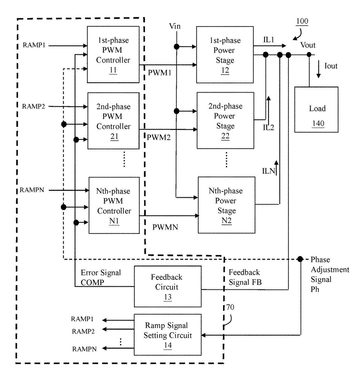
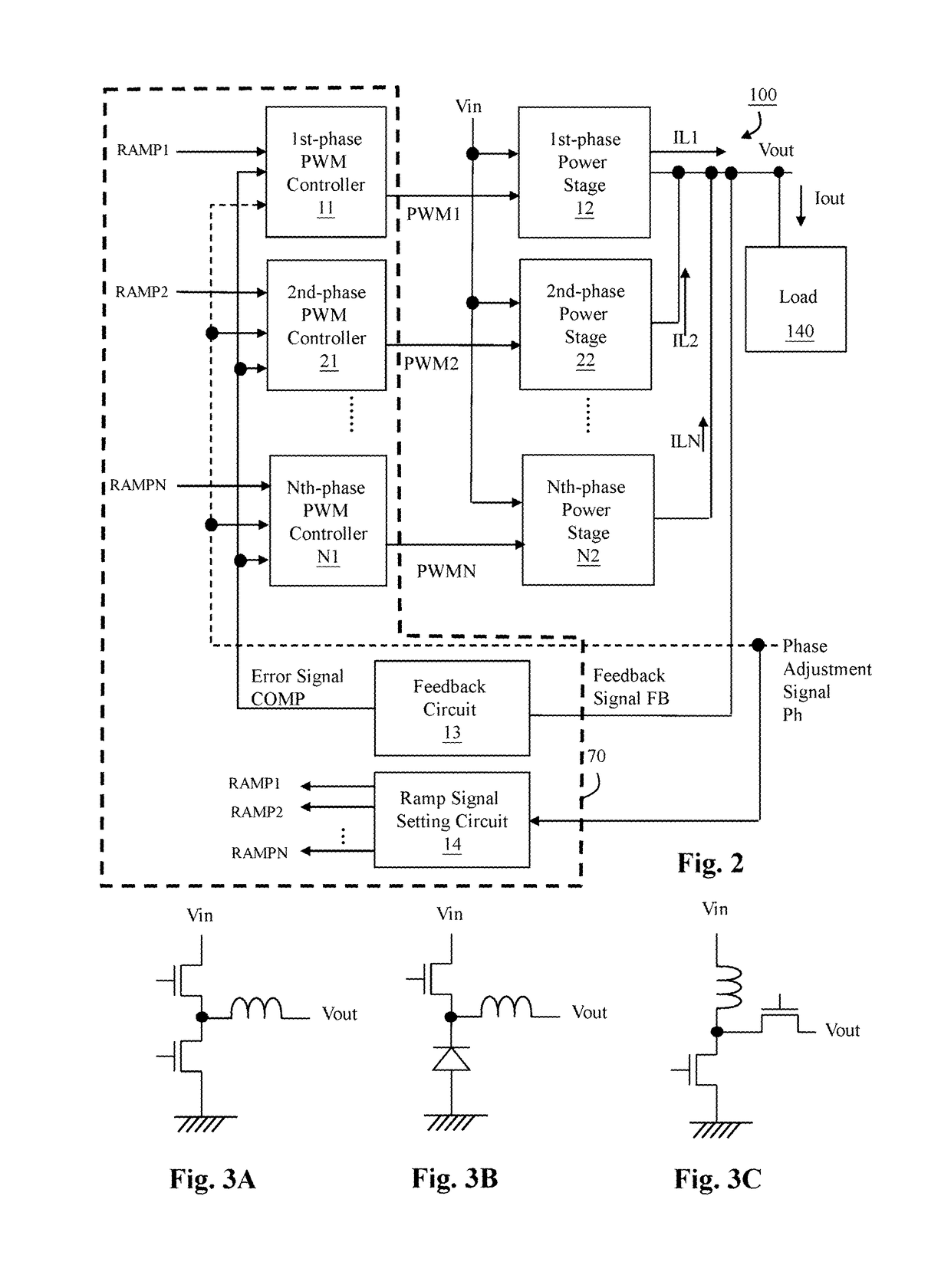
[0036]The fundamental spirit of the present invention lies in that: when it is required to reduce or increase the number of active phases of the power stages of a multi-phase switching regulator, such as under a transition between a light load condition and a heavy load condition, the multi-phase switching regulator of the present invention is capable of adjusting a ramp signal which is related to a phase to be enabled or disabled according to the phase adjustment signal.

[0037]That is, on one hand, when the multi-phase switching regulator is under a phase...


PUM


Abstract

A multi-phase switching regulator includes: a plurality of power stages, a plurality of pulse width modulation (PWM) controllers and a ramp signal setting circuit. The PWM controllers generate corresponding PWM signals for controlling corresponding power stages respectively according to an error signal related to an output voltage and a plurality of ramp signals corresponding to corresponding power stages respectively. The ramp signal setting circuit adjusts the ramp signal of the phase that is to be enabled or disabled according to the phase adjustment signal. Under a phase-cut operation, the ramp signal setting circuit causes a basis level of the ramp signal corresponding to the phase to be disabled to gradually change, thereby decreasing a duty ratio of the PWM signal corresponding to the phase to be disabled.

Description

CROSS REFERENCE[0001]The present invention claims priority to TW 106124464 filed on Jul. 21, 2017.BACKGROUND OF THE INVENTIONField of Invention[0002]The present invention relates to a multi-phase switching regulator and a control circuit and a control method thereof; particularly, it relates to such multi-phase switching regulator, control circuit and control method which can avoid an undesirable undershoot or overshoot of the output voltage during a transition period of “phase add” or “phase cut” operation.Description of Related Art[0003]Please refer to FIG. 1, which shows a wave form of a conventional multi-phase switching regulator when it is under a phase adjustment operation.[0004]A multi-phase switching regulator is controlled to adapt the number of active phases to the load conditions, by reducing or increasing the number of phases depending on the current required by the load. For example, the number of phases is reduced (i.e. “phase cut”) at a light load condition, the numb...

Claims


Application Information

Patent Timeline
Patent Type & Authority Patents(United States)
IPC IPC(8): H02M3/158
CPCH02M3/1584H02M2003/1586H02M3/1586
Inventor HO, JYUN-CHECHEN, YU-CHANGWANG, JO-YULEE, YI-WEICHEN, ISAAC Y.
Owner RICHTEK TECH
Why Eureka
Eureka Blog
Learn More