Power conversion system

Active Publication Date: 2021-03-18
DELTA ELECTRONICS INC
View PDF0 Cites 3 Cited by
  • Summary
  • Abstract
  • Description
  • Claims
  • Application Information

AI Technical Summary

Benefits of technology

The present patent provides a power conversion system with a multi-phase buck converter that has an extended duty ratio. This system increases the duty ratio and reduces the amount of voltage jump during switch turn-on or-off, which reduces switching loss and improves efficiency. Additionally, the system includes a bootstrap circuit and a driving circuit, which enhances its applicability and benefits in miniaturizing the power conversion system product. The bootstrap circuit is simple and low-cost.

Problems solved by technology

However, in the buck circuit, the switching duty ratio equals the voltage transmission ratio of the output voltage to the input voltage, i.e., Vo=Vin*D. Accordingly, in the applications that the input voltage is larger than the output voltage, the switching duty ratio is reduced, which causes the buck circuit unable to operate with the best performance.

Method used


Image

  • Power conversion system
  • Power conversion system
  • Power conversion system

Examples


first embodiment

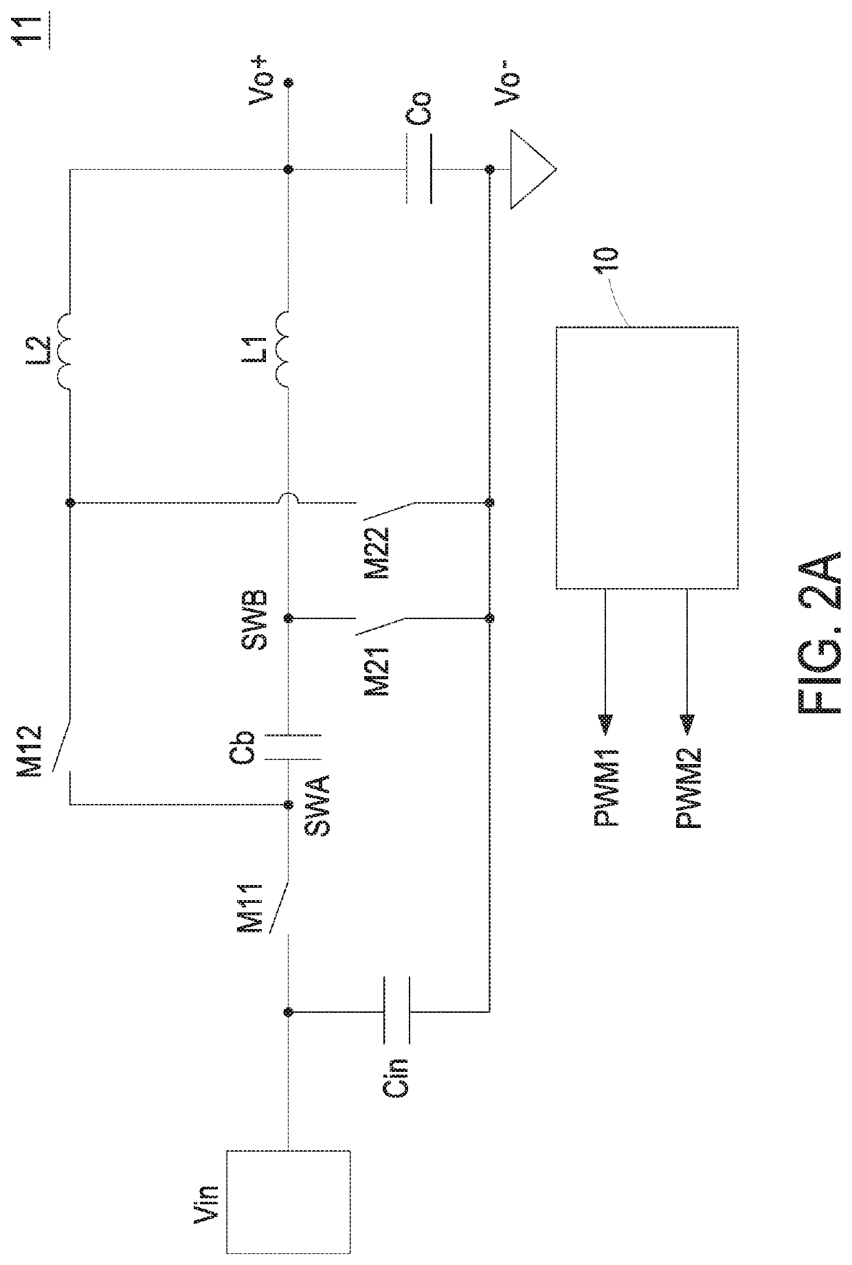
[0060]In the first embodiment shown in FIG. 4A, N equals 2, and the power conversion circuit 11 includes two switching power conversion units and one storage device. The storage device is the capacitor Cb, and there are the first node SWA and the second node SWB at the two ends of the capacitor Cb respectively. The first switching power conversion unit includes a first switch M11, a second switch M21 and an inductor L1. The second switching power conversion unit includes a first switch M12, a second switch M22 and an inductor L2. Please refer to FIG. 3A and FIG. 3B, Ts is the switching period, and D is the duty ratio of the switching period. FIG. 3A and FIG. 3B shows the switch driving signals of the power conversion circuit 11 with D smaller than 50% and D larger than 50% respectively. The control sequences of the first switches M11 and M12 are 180 degrees out of phase with respect to each other. The driving signals of the first and second switches M11 and M21 are complementary to ...

second embodiment

[0062]In the second embodiment shown in FIG. 5A, N equals 2, the power conversion circuit 11 is similar to the power conversion circuit 11 of FIG. 2A and FIG. 4A, and the detailed description thereof is omitted herein. The turns ratio of the magnetic element T1 of the power circuit 22 to the winding T3 of the precharge circuit 32 is 2:1, and the winding T3 is positively coupled to the magnetic element T1. Please refer to the oscillogram shown in FIG. 5B. When the sixth switch S3 is turned on, the voltage VT1 on the magnetic element T1 equals Vin, the voltage on the winding T3 equals Vin / 2, and the third diode D3 is turned on. Therefore, the voltage VC3 on the third capacitor C3 equals Vin / 2. When the sixth switch S3 is turned off, the supply voltage Vcc is provided through the negative coupling between the winding T4 and the magnetic element T1. Meanwhile, the voltage VC3 on the third capacitor C3 charges the capacitor Cb through the third resistor R3 and the fourth resistor R4, whi...

third embodiment

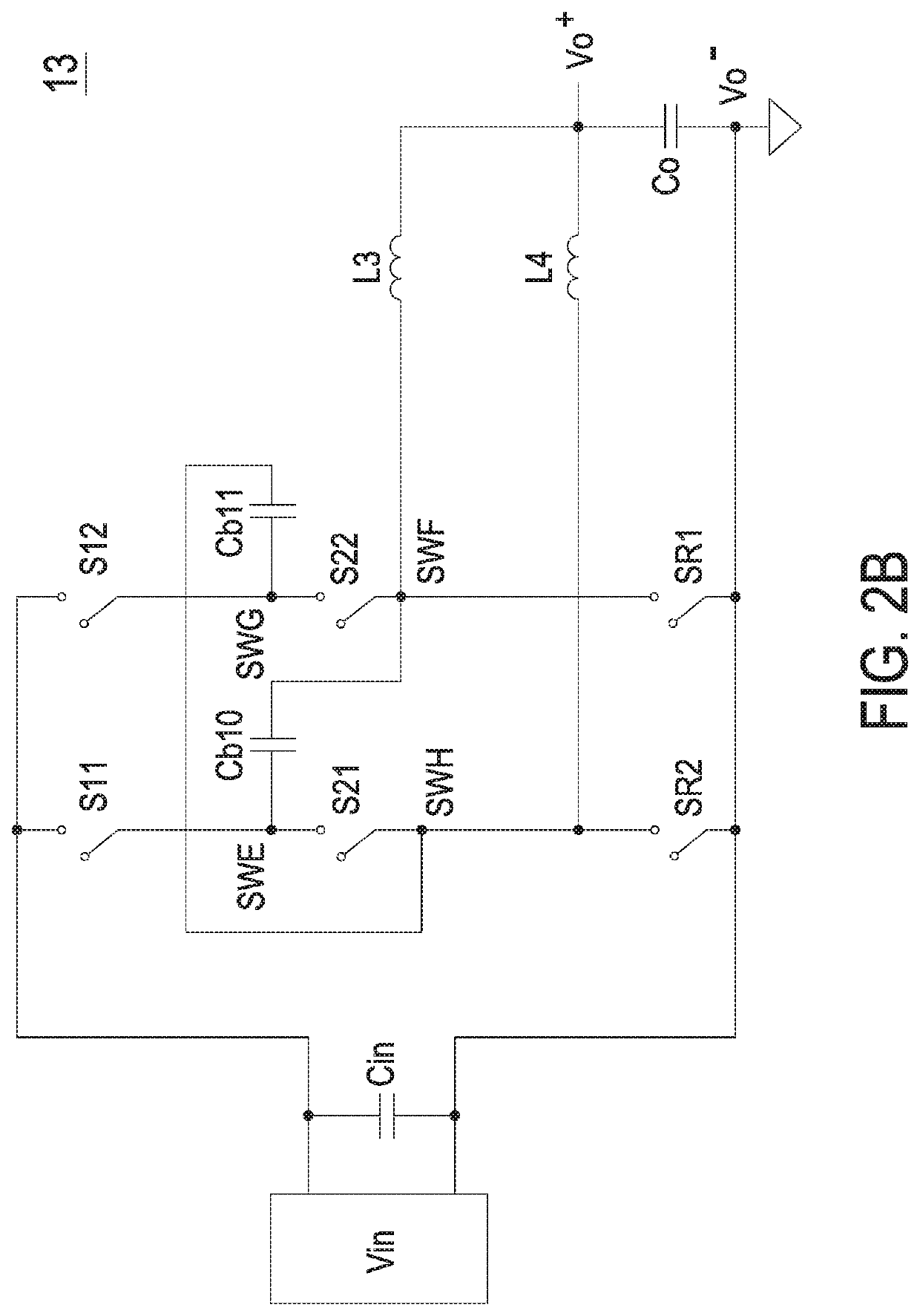
[0071]In the third embodiment shown in FIG. 5C, N equals 2, and the second power conversion circuit 13 includes two switching power conversion units and two storage devices. The first switching power conversion unit includes a first switch S11, a second switch S22, a third switch SR1 and an inductor L1. The second switching power conversion unit includes a first switch S12, a second switch S21, a third switch SR2 and an inductor L2. The storage devices are the capacitors Cb10 and Cb11. There are the first node SWE and the second node SWF at two ends of the capacitor Cb10 respectively, and there are the first node SWG and the second node SWH at two ends of the capacitor Cb11 respectively. Please refer to FIG. 3C, where Ts is the switching period, and D is the duty ratio of the switching period. The first switch S11 and the second switch S22 are turned on and off simultaneously, and the first switch S12 and the second switch S21 are turned on and off simultaneously. The control sequen...


PUM


Abstract

A power conversion system is provided. The power conversion system includes a power conversion circuit, a bootstrap circuit and at least N driving circuits, where N is an integer larger than 1. The power conversion circuit includes an input port, an output port, N switching power conversion units and N nodes. The switching power conversion unit includes a first switch and a second switch. The bootstrap circuit includes N bootstrap capacitors and N bootstrap switches. The N bootstrap switches are serially connected in sequence. Two ends of the bootstrap capacitor are connected to the corresponding node and the second terminal of the corresponding bootstrap switch respectively. The first terminal of the (N)th bootstrap switch receives a supply voltage. The driving circuit is connected to the corresponding bootstrap capacitor and outputs driving signals for controlling the switches according to the positive electrode voltage of the bootstrap capacitor.

Description

CROSS-REFERENCE TO RELATED APPLICATION[0001]This application claims priority to China Patent Application No. 201910883647.6 filed on Sep. 18, 2019 and claims priority to China Patent Application No. 202010772969.6 filed on Aug. 4, 2020. The entire contents of the above-mentioned patent applications are incorporated herein by reference for all purposes.FIELD OF THE INVENTION[0002]The present disclosure relates to a power conversion system, and more particularly to a power conversion system having a bootstrap circuit.BACKGROUND OF THE INVENTION[0003]In conventional applications of non-isolated step-down DC-DC converters with high output current, a two-phase buck circuit with parallel configuration is employed. As shown in FIG. 1, the parallel configuration is utilized to reduce the current stress on switches, and the switches in every phase of the buck circuit are driven by two signals having 180 degrees out of phase with respect to each other, so as to reduce the current ripple. Howe...

Claims


Application Information

Patent Timeline
IPC IPC(8): H02M3/158H02M3/07H02M3/335
CPCH02M3/1584H02M3/07H02M2001/0003H02M2003/1586H02M3/33576H02M3/1586H02M1/007H02M1/0003
Inventor JIN, DAXIONG, YAHONGSU, QINGHUA
Owner DELTA ELECTRONICS INC
Why Eureka
Try Eureka