
Method and system for improving amplifier efficiency

Inactive Publication Date: 2005-03-31
TEXAS INSTR INC
View PDF8 Cites 0 Cited by
  • Summary
  • Abstract
  • Description
  • Claims
  • Application Information

AI Technical Summary

Benefits of technology

From the foregoing, it may be appreciated that a need has arisen for providing a system and method to improve efficiency for amplifier applications. In accordance with the present invention, a system and method are provided that substantially eliminate or reduce disadvantages and problems of conventional amplifier systems.

Problems solved by technology

Thus, in many applications where low distortion is desirable, performance may suffer from low amplifier efficiency.
However, such conventional designs may not sufficiently improve amplifier efficiency to meet a desired level of performance.
For example, these conventional designs may still suffer from low signal-to-noise ratios and / or dynamic range.

Method used


Image

  • Method and system for improving amplifier efficiency
  • Method and system for improving amplifier efficiency
  • Method and system for improving amplifier efficiency

Examples


Embodiment Construction

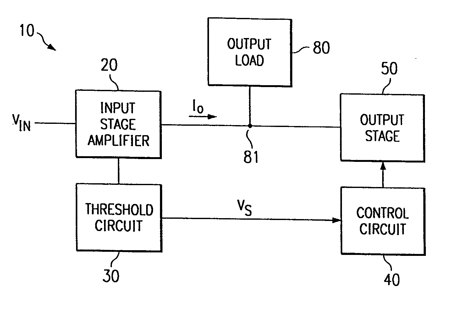
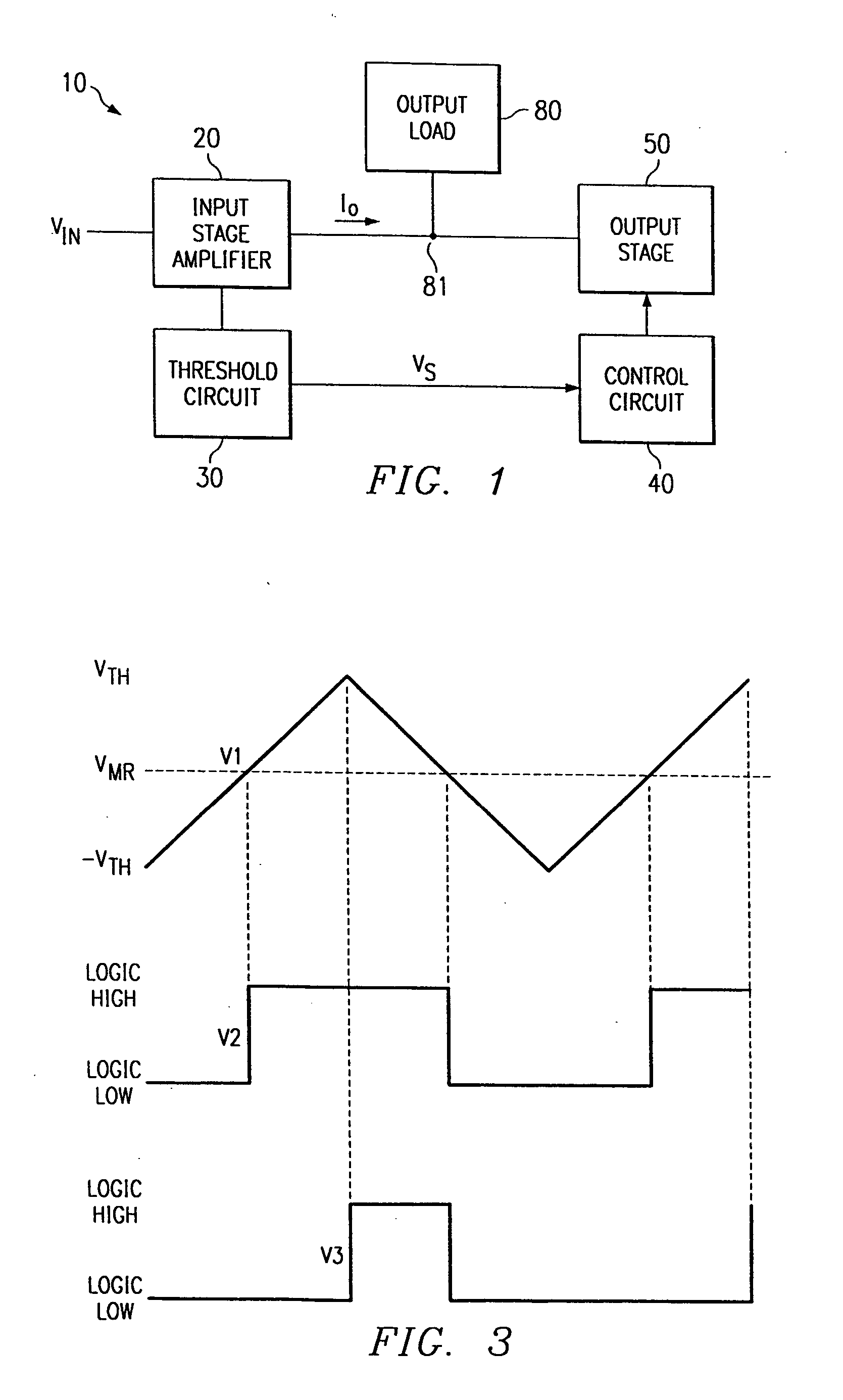
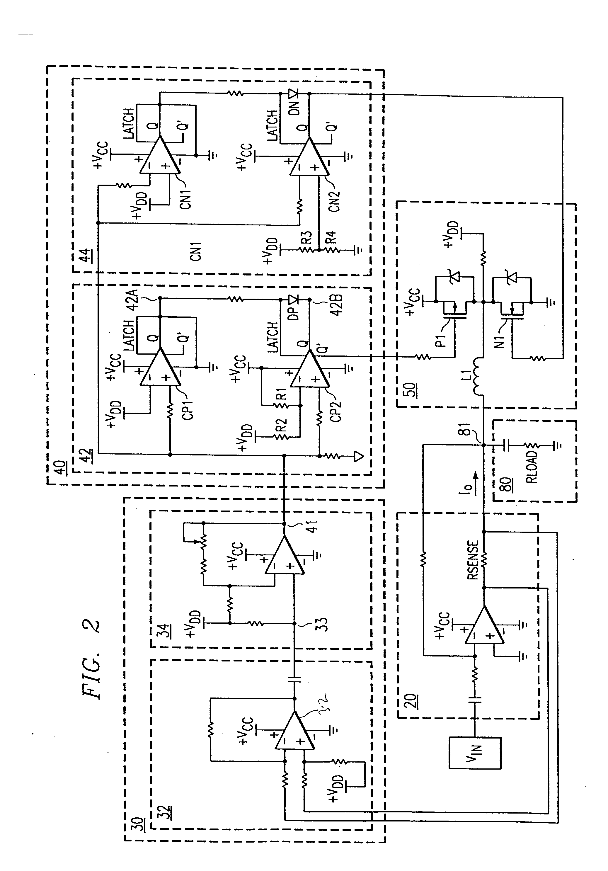
FIG. 1 illustrates a block diagram of an amplifier system 10. Amplifier 10 includes an input stage amplifier 20 coupled to an input voltage VIN, a threshold circuit 30 and an output load 80. Amplifier system 10 also includes a control circuit 40 coupled to threshold circuit 30 and to output stage 50. Output stage 50 is also coupled to output load 80. Although direct connections are illustrated for various elements, many elements may be coupled through other elements without departing from the scope of the invention. As further detailed below, control circuit 40 may be coupled to and may control any class D output stage 50. Control circuit 40 is operable to control the current flowing to output load 80 by activating and deactivating switches within output stage 50 in response to a measured value that senses the amount of current flowing to output load 80. Such control of current flowing to output load 80 may improve the efficiency of amplifier system 10.

Input stage amplifier 20 cont...


PUM


Abstract

One aspect of the invention is an amplifier (10), comprising an input stage amplifier (20) coupled to an output node (81). The amplifier (10) further comprises a class D output stage (50), which comprises at least two switching elements (P1, N1) and coupled to the output node (81). The amplifier (10) also comprises a control circuit (40) coupled to the output stage (50). The control circuit (40) is operable to produce a tri-state output of the output stage (50) in response to a sensed value proportional to an amount of current that flows to the output node (81).

Description

TECHNICAL FIELD OF THE INVENTION This invention relates generally to the field of amplifier circuits and more particularly to a method and system for improving amplifier efficiency. BACKGROUND OF THE INVENTION Amplifiers are used to increase or decrease voltage levels in many applications. Proper amplifier design, whether within discrete or integrated circuits, often involves tradeoffs of amplifier characteristics such as efficiency and distortion. Thus, in many applications where low distortion is desirable, performance may suffer from low amplifier efficiency. Conventional amplifiers, including audio amplifiers, may employ a plurality of stages in order to improve amplifier performance. For example, some amplifier designs may utilize both an input stage that features characteristics such as low distortion and an output stage that resembles a class D stage that typically features higher efficiency. Such a combination may improve the total efficiency of the amplifier. However, su...

Claims


Application Information

Patent Timeline
IPC IPC(8): H03F3/217H03F3/45
CPCH03F1/0277H03F2200/432H03F3/45475H03F3/2171
Inventor STEPHENS, RANDALL J.THOMAS, TEDDY D.
Owner TEXAS INSTR INC
Learn More